Live tooling systems for machine tools

a tooling system and machine tool technology, applied in the direction of turning machines, printing, forging hammers, etc., can solve the problems of tool tip being caused to move forcefully downwards against the workpiece, acceleration of the tooling,

Active Publication Date: 2009-01-08
WILSON TOOL INT
View PDF9 Cites 2 Cited by
  • Summary
  • Abstract
  • Description
  • Claims
  • Application Information

AI Technical Summary

Benefits of technology

[0029]Optionally, the power source can be adapted to deliver electric current so as to energize a laser marking head of the tool.

Problems solved by technology

Thus, when the ram strikes the top of the tool (which is rigidly coupled to the tip of the tool), the tip of the tool is caused to move forcefully d

Method used


Image

  • Live tooling systems for machine tools
  • Live tooling systems for machine tools
  • Live tooling systems for machine tools

Examples


Embodiment Construction

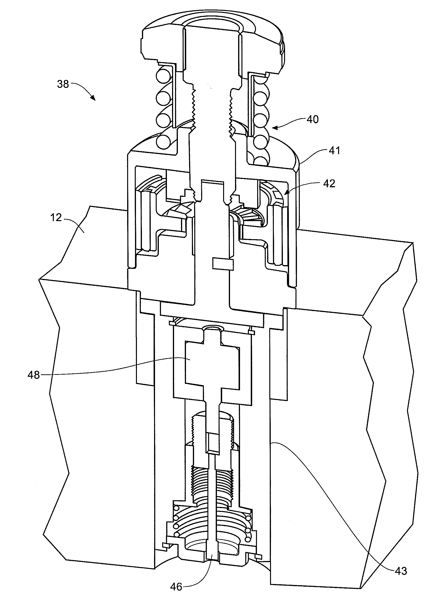
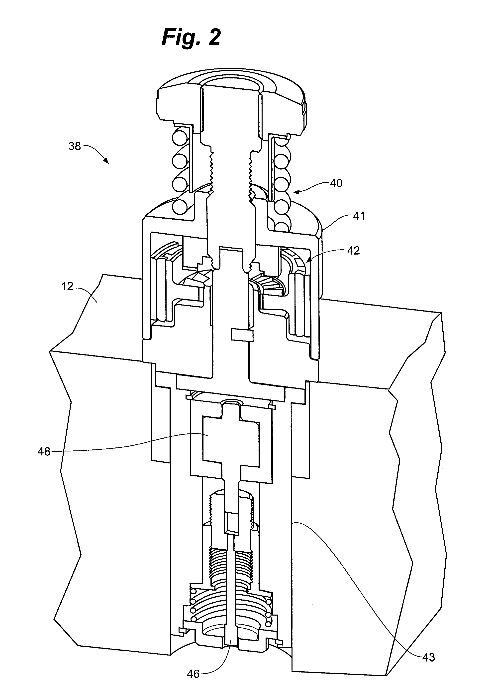
[0051]The following detailed description is to be read with reference to the drawings, in which like elements in different drawings have like reference numerals. The drawings, which are not necessarily to scale, depict selected embodiments and are not intended to limit the scope of the invention. Skilled artisans will recognize that the given examples have many useful alternatives, which fall within the scope of the invention. In particular, it should be noted that, although a majority of embodiments of the present invention are shown and described in the context of a turret-style punch press, the invention is not so limited and alternative embodiments may be employed in any other style or type of press, for example, including single station punch presses.

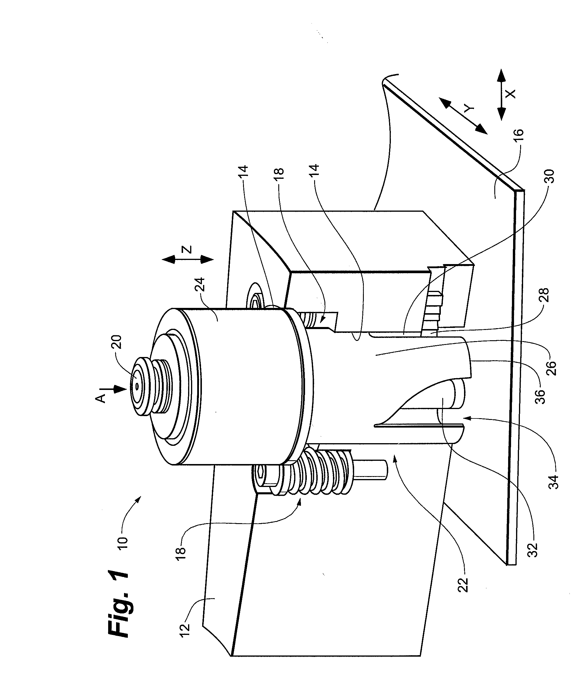
[0052]FIG. 1 is a perspective view of a tool assembly 10, according to certain embodiments of the present invention, assembled to be used in a portion of a press. As described above, the press is used for fabricating metal. FIG. 1 ...


PUM

PropertyMeasurementUnit
Forceaaaaaaaaaa
Poweraaaaaaaaaa
Accelerationaaaaaaaaaa

Abstract

In conventional ram-driven presses, the downward stroke of the ram into a tool causes acceleration of the tool, thereby facilitating an operation on a workpiece by the tip of the tool. While the ram stroke is found to impart sufficient dynamic energy to the tool to facilitate the necessitated operation by the tool tip, there are other more efficient, and in turn, more effective, means and methods of actuating the tool tip, with such means and methods being facilitated from energy derived from the tool's acceleration or from energy from other external sources.

Description

CROSS REFERENCE TO RELATED APPLICATIONS[0001]The present application claims priority to U.S. provisional application No. 60 / 914,468, filed Apr. 27, 2007, the disclosure of which is incorporated herein by reference.FIELD OF THE INVENTION[0002]The present invention relates generally to assemblies and methods for tooling systems used with industrial presses. In particular, this invention relates to assemblies and methods employed by metal-fabricating presses.BACKGROUND OF THE INVENTION[0003]Ram-driven presses, e.g., punch presses, are well known in the art. Punch presses are typically configured to hold a plurality of tools for forming a variety of shapes and sizes of indentations and / or holes in sheet workpieces, e.g., sheet metal. Tools of this sort commonly include a punch and die. When a punch and corresponding die are mounted in a press and located in a working position of the press, e.g., beneath the ram (in some cases, coupled directly to the ram), the punch is driven, according...

Claims


Application Information

Patent Timeline
IPC IPC(8): B26D5/08B22F3/24
CPCB21D28/002Y10T29/519B21D28/26B23B43/00B23G3/005B23K26/0093B30B15/148B41J3/413H02K7/07H02K7/14H02K7/1807H02K7/1892H02K21/14Y10T29/5153B21D28/12Y10T83/8727Y10T83/8732Y10T83/8748
Inventor LEE, BRIAN J.SHIMOTA, JON M.
Owner WILSON TOOL INT
Why Eureka
Try Eureka