
Temperature Indicator

a technology of temperature indicators and indicators, applied in the field of temperature indicators, can solve the problems of incorrect impression of cold iron by users, and the indicator does not give any information as to which part of the surface, and achieves the effect of low cos

Inactive Publication Date: 2009-01-08
KONINKLIJKE PHILIPS ELECTRONICS NV
View PDF9 Cites 5 Cited by
  • Summary
  • Abstract
  • Description
  • Claims
  • Application Information

AI Technical Summary

Benefits of technology

[0004]An object of the present invention is to provide a temperature indicator which accurately and at low cost provides a safe indication of whether a surface is hot or not.

Problems solved by technology

A disadvantage with the type of temperature indicator described in U.S. Pat. No. 6,396,027 B1 is that it is complicated and requires the proper cooperation between several components in order to perform accurately in warning a user for high temperatures.
A broken lamp may, as an example, give the user the incorrect impression that the iron is cold when it in reality is hot.
Furthermore, a temperature indicator of this type does not give any information as regards which part of the surface that is hot, if it is the entire surface or only a part of it.

Method used


Image

  • Temperature Indicator
  • Temperature Indicator
  • Temperature Indicator

Examples


first embodiment

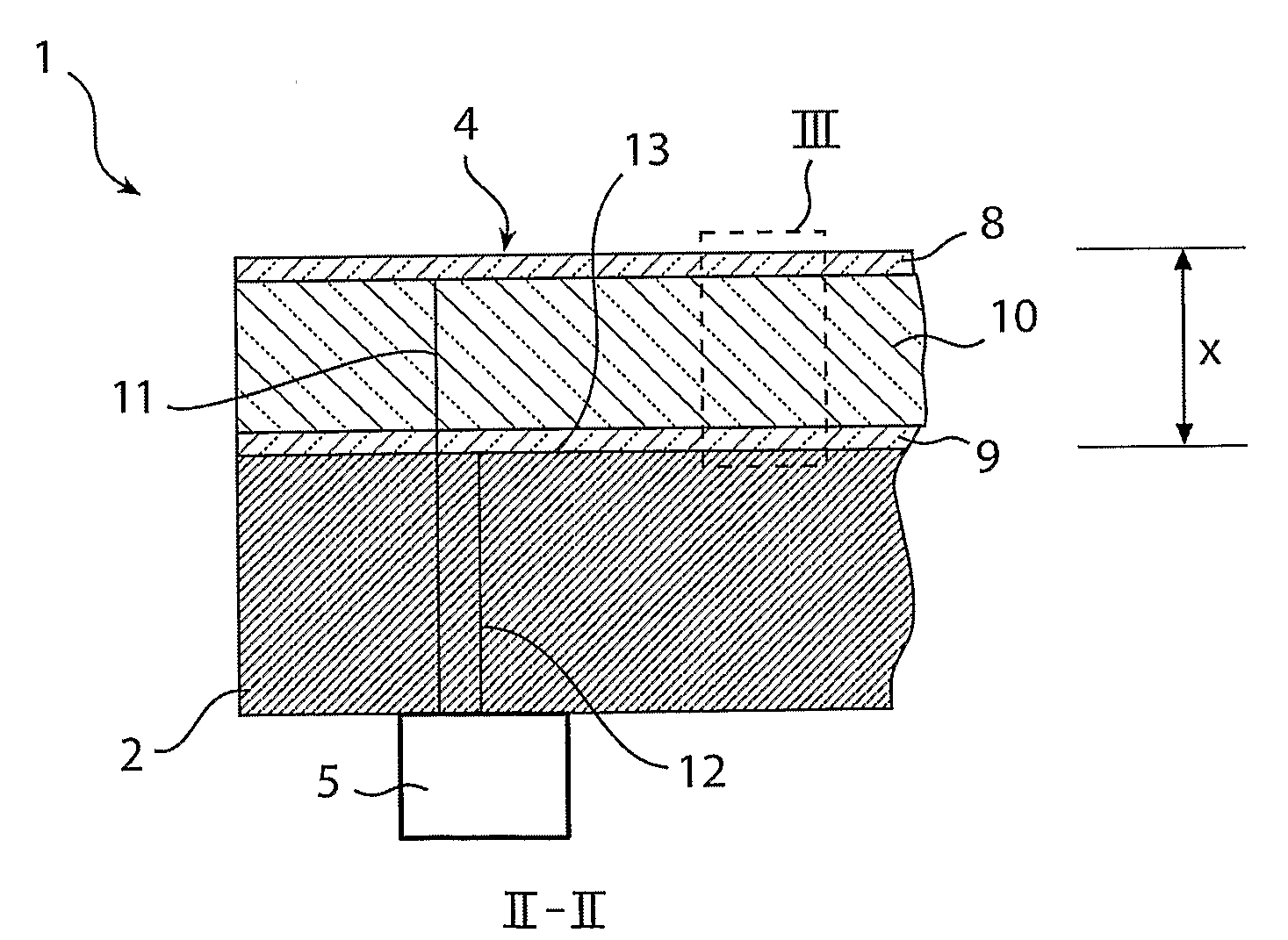
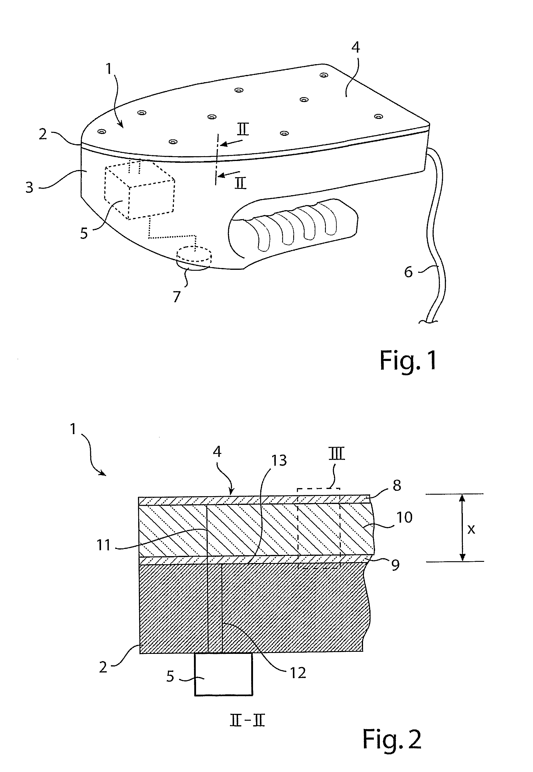
[0038]FIG. 1 shows schematically a temperature indicator 1 according to the invention. The temperature indicator 1 covers the entire sole 2 of an iron 3. The temperature indicator 1 comprises a light-emitting electrochemical cell 4 and an AC power source 5 adapted to drive the light-emitting electrochemical cell 4 with a low frequency AC voltage. The AC power source 5 is connected to the main electricity system (not shown in FIG. 1) of the iron 3 and provides the light-emitting electrochemical cell 4 with an AC voltage all the time the electrical cable 6 of the iron 3 is connected to a power supply. An AC voltage frequency modulator 7 could optionally be included in the temperature indicator 1 in order to enable fine tuning of the temperature at which a light emission should start, as will be explained below.

[0039]FIG. 2 is a cross section showing the light-emitting electrochemical cell 4 having the shape of a thin laminate provided on the sole 2. The light-emitting electrochemical ...

second embodiment

[0058]FIG. 6 is a cross section and illustrates, schematically, a temperature indicator 101 according to the invention. This temperature indicator 101 is attached to the outer surface 113 of a window 102 of a household oven door 103 having, on the outside, a handle 106. The temperature indicator 101 comprises a light-emitting electrochemical cell 104, which has the form of a thin laminate, and an AC power source 105 adapted to drive the light-emitting electrochemical cell 104 with a low frequency AC voltage. The AC power source 105 is connected to the main electricity system (not shown in FIG. 1) of the oven. A preferred way of activating the power source 105 is to have it activated automatically as soon as the oven is activated and allow the power source 105 to remain activated for a certain time, e.g. 30 minutes, after the controls of the oven has been put to “0° C.”.

[0059]The light-emitting electrochemical cell 104 comprises a first electrode 108, a second electrode 109 and a lig...


PUM


Abstract

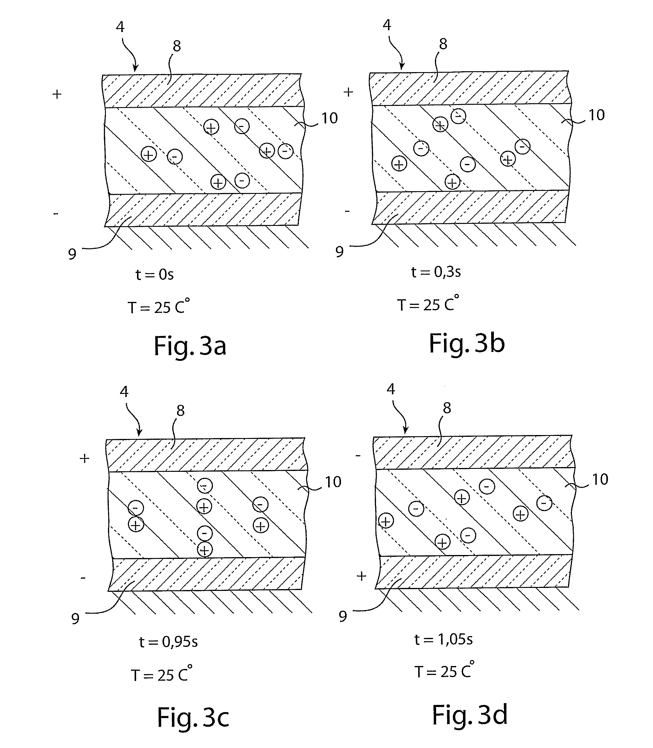
A temperature indicator (1) for indicating a high temperature at a surface (13) comprises a light-emitting electro-chemical cell (4) having a first electrode (8), a second electrode (9) and a light-emitting layer (10) being sandwiched between the two electrodes (8, 9). The light-emitting layer (10) comprises a matrix and ions being movable in the matrix, the mobility of said ions in said matrix being temperature dependent. A power source (5) is adapted for driving the light-emitting cell (4) with an AC voltage. The frequency of the AC voltage is tuned in such a way that, above a certain temperature level, the ions move fast enough in the matrix to provide a sufficient charge gradient in the light-emitting electrochemical cell (4) for the light-emitting electrochemical cell (4) to emit light before the AC power source (5) shifts the polarity of the voltage.

Description

FIELD OF THE INVENTION[0001]The present invention relates to a temperature indicator adapted to be provided on a surface for providing a visual indication of the temperature of the surface.[0002]The present invention also relates to a method of forming a temperature indicator adapted to be provided on a surface for providing a visual indication of the temperature of the surface.BACKGROUND OF THE INVENTION[0003]In many appliances hot temperatures are involved during use. Examples of such appliances are irons, water cookers, hot plates, oven windows, frying pans, toasters, waffle irons etc. In order to avoid injuries, such as burn injuries, to persons using such appliances there is a need to have an indicator indicating to the person using the appliance that it is hot and that care must be taken. Such indication of a high temperature is usually done by having a temperature sensor, a control unit coupled to the sensor and a warning lamp, which is lit by the control unit when the sensor...

Claims


Application Information

Patent Timeline
IPC IPC(8): G01K11/00
CPCG01K11/12
Inventor MEIJER, EDUARD JOHANNESKURT, RALPH
Owner KONINKLIJKE PHILIPS ELECTRONICS NV
Learn More