
Toothbrush Sterilizer

a sterilizer and tooth brush technology, applied in the field of tooth brush sterilizers, can solve the problems of affecting the sterilization effect of the tooth brush, so as to prevent the contamination of the bristles or discoloration, increase the fastening force of the sterilization lamp, and prevent the effect of contamination

Inactive Publication Date: 2009-01-08
ESENCIA
View PDF5 Cites 29 Cited by
  • Summary
  • Abstract
  • Description
  • Claims
  • Application Information

AI Technical Summary

Benefits of technology

[0031]The toothbrush sterilizer of the present invention employs a magnet on its pivoting cover and a lead switch on its main body opposite the cover to illuminate its sterilizing lamp only when the cover is closed. Because the switch does not protrude out from the main body, the turning on of the switch manually and ultraviolet rays emitted to the outside as a result can be prevented.
[0032]The toothbrush sterilizer has a fixing holder at the bottom of the sterilizing lamp. The lamp is inserted through the fixing holder into the socket, and the holder is fixed through protrusions so that the fastening force of the sterilizing lamp is increased. Thus, attaching and detaching the lamp for replacement is easier.
[0033]The toothbrush sterilizer has a plurality of toothbrush holders that are detachable from the main body and a reflective plate formed around the sterilizing lamp. The toothbrush holders hold the toothbrushes upright and lack a surface contacting the bristles, to prevent contamination of the bristles or discoloring of the holders. The reflective plate reflects and widens the range covered by the ultraviolet rays from the sterilizing lamp, so that sterilizing effectiveness of the unit increases.
[0034]The toothbrush sterilizer has a fan at the rear of the main body. The fan operates to vent air into the main body, so that when a dryer and the sterilizing lamp radiate heat, the sterilizing capacity increases, and the sterilizing lamp can be operated for a long duration.
[0035]The toothbrush sterilizer has a pin protruding from the bottom of the main body for pressing the limit switch. In this way, a double safety mechanism is provided with this safety switch that senses whether the main body is securely placed on a floor, in order to prevent manual activation of the sterilizing lamp.
[0036]The toothbrush sterilizer has a detachable stand forming a water pan at the bottom of the main body, in order to prevent random dispersion of water that drains from toothbrushes stored in the main body onto the floor. Because the stand holds the water, contamination of the main body floor can be prevented.

Problems solved by technology

However, due to the inconvenience caused by a user having to manually turn the switch on and off, a limit switch has recently found favor.
However, in the above configuration, the limit switch may be pressed manually when the cover is open, so that the sterilizing lamp is activated and ultraviolet rays are emitted to the outside of the unit, which may cause burns.
When the sterilizing lamp is detached from the socket to replace the lamp, the coupling portion can be easily damaged.
Especially in the case of vertically disposed sterilizing lamps, the lower portion of the lamp is fixed to the socket, so that even small shocks or vibrations cause severe movement of the lamp.
Consequently, there is the possibility that the lamp may collide with the main body and be damaged, or that an electrode pin inserted into the socket may be severed.
However, because the toothbrush bristles rest on the top surfaces of the elastic arms, the regions on the elastic arms that contact the bristles discolor, and the contaminants thereon may be transferred to the bristles.
Thus, a user is inconvenienced by having to frequently clean the toothbrush holders.
Furthermore, a separate water pan is not provided at the bottom of the main body, so that when water drains down from toothbrushes held in the holders, the water contaminates the floor of the unit.

Method used


Image

  • Toothbrush Sterilizer
  • Toothbrush Sterilizer
  • Toothbrush Sterilizer

Examples


Embodiment Construction

[0051]Reference will now be made in detail to the preferred embodiments of the present invention, examples of which are illustrated in the accompanying drawings. Wherever possible, the same reference numbers will be used throughout the drawings to refer to the same or like parts.

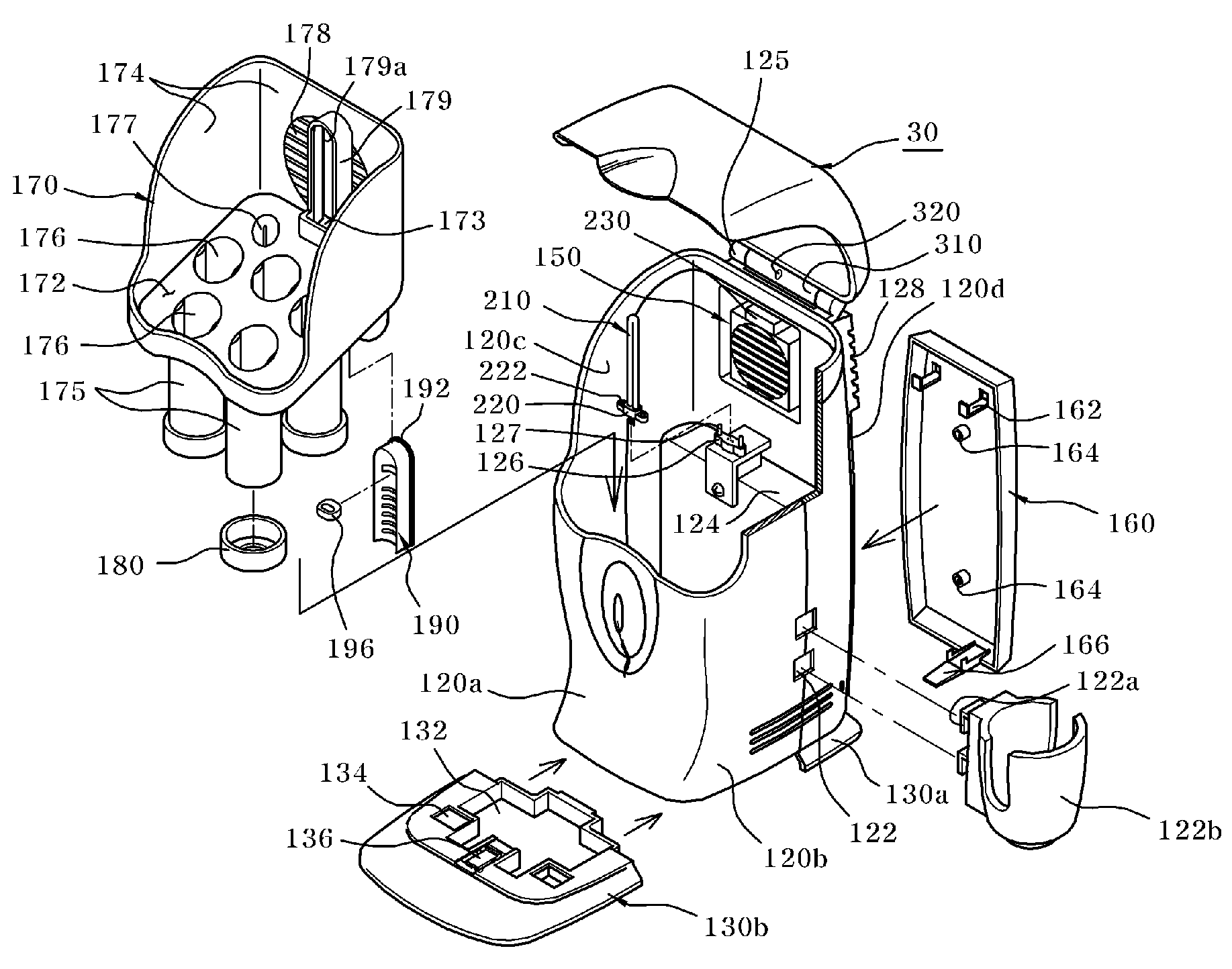
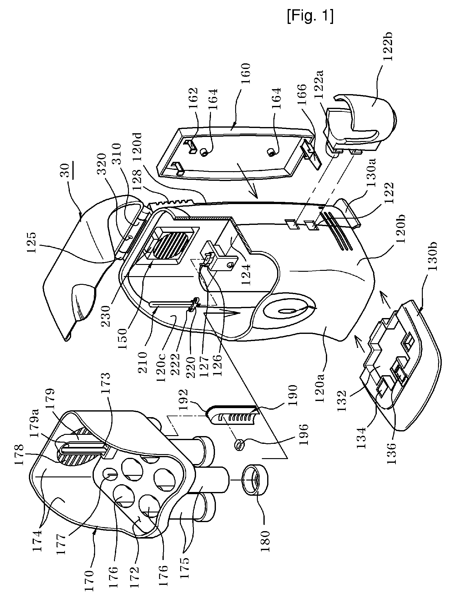
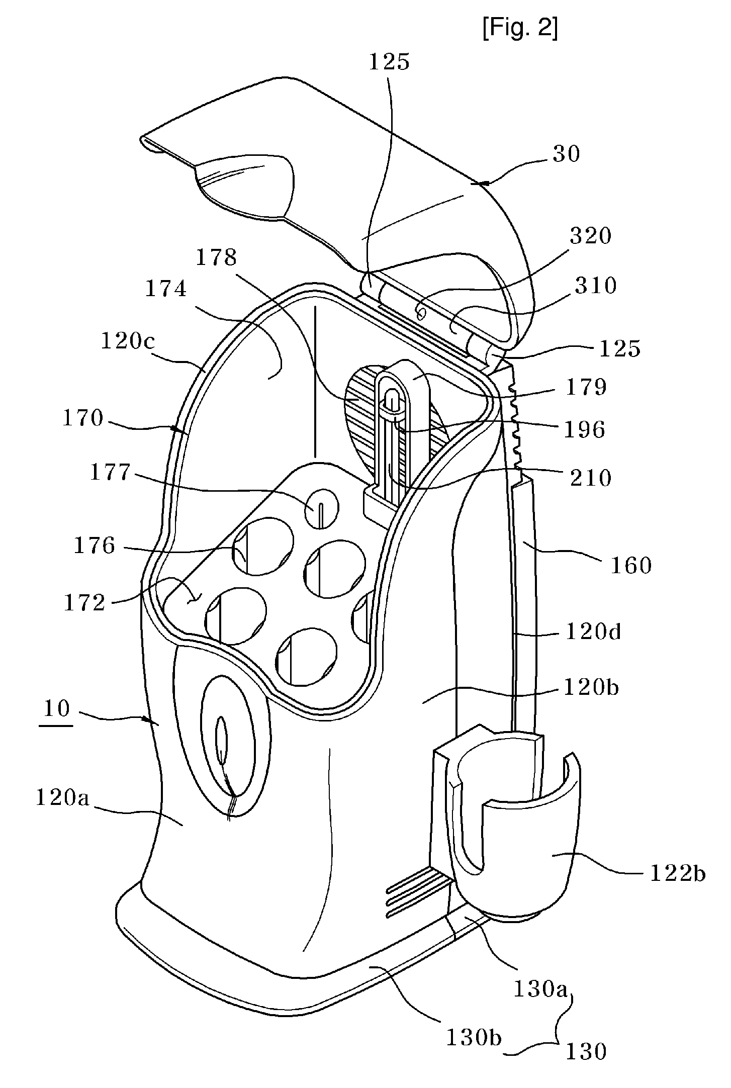
[0052]FIG. 1 is an exploded perspective view of a toothbrush sterilizer according to the present invention, FIG. 2 is a perspective view of a toothbrush sterilizer with a pivoting cover according to the present invention, and FIG. 3 is a sectional view of a toothbrush sterilizer with its cover closed according to the present invention. Referring to FIGS. 1 through 3, a toothbrush sterilizer is open at one side and includes a main body 10 for storing toothbrushes, an ultraviolet ray emitter 20 provided in the main body 10 for emitting ultraviolet rays, and a cover 30 for closing the open portion of the main body 10.

[0053]In further detail, the main body 10 includes a bottom surface 110 and side walls 120a, 12...


PUM

PropertyMeasurementUnit
perimeteraaaaaaaaaa
distanceaaaaaaaaaa
inner diameteraaaaaaaaaa

Abstract

A toothbrush sterilizer is provided. The toothbrush sterilizer employs a magnet on its pivoting cover and a lead switch on its main body opposite the cover to illuminate its sterilizing lamp only when the cover is closed, has a detachable toothbrush storage compartment, has a lamp holder that allows easy replacement of the sterilizing lamp and a detachably mounted stand with a water receiving area, and is easy to use and maintain in a hygienic state. The toothbrush sterilizer includes a storage compartment detachably attached inside the main body. The storage compartment has a plate, a side wall erected around a perimeter of the plate, and a plurality of insert holes formed in and extending a predetermined distance down from the plate, for storing the toothbrushes therein.

Description

TECHNICAL FIELD[0001]The present invention relates to a toothbrush sterilizer, and more particularly, to a toothbrush sterilizer that employs a magnet on its pivoting cover and a lead switch on its main body opposite the cover to illuminate its sterilizing lamp only when the cover is closed, allows a compartment for storing toothbrushes to be detached from the main body, allows easy replacement of the sterilizing lamp due to a sterilizing lamp holder, has a detachably mounted stand forming a water receiving area at the bottom of the main body, and is easy to use and maintain in a hygienic state.BACKGROUND ART[0002]A toothbrush sterilizer is a device that uses a sterilizing lamp that emits ultraviolet rays to sterilize toothbrush bristles, and includes a main body, holders for storing toothbrushes, and a sterilizing lamp.[0003]Such toothbrush sterilizers according to the related art are divided into portable toothbrush sterilizers and standing units that are furnished and used in a b...

Claims


Application Information

Patent Timeline
Patent Type & Authority Applications(United States)
IPC IPC(8): A61L2/10
CPCA61L2/10E05D11/06E05D3/02F16C11/04
Inventor SHIN, CHOONG-SIK
Owner ESENCIA
Learn More