
Design support system, method and program

a support system and design technology, applied in the field of design support system, method and program, can solve the problems of inability to calculate the difference between different shapes, distortion, stress and temperature, and other positions than the nodes, and achieve the effect of easy determination or recognition

Inactive Publication Date: 2009-01-08
TOYOTA JIDOSHA KK
View PDF4 Cites 6 Cited by
  • Summary
  • Abstract
  • Description
  • Claims
  • Application Information

AI Technical Summary

Benefits of technology

[0015]According to the invention, attribute differences at nodes and attribute calculation points other than the nodes between different shapes can be easily calculated. Also, the attribute differences are displayed on the screen while being distinguished from one another, so that the condition of the distribution of the attribute differences can be easily determined or recognized.

Problems solved by technology

However, according to the techniques as disclosed in JP-A-2005-266894 and JP-A-2005-208735, differences in attributes, such as distortion, stress and temperature, at the nodes and other positions than the nodes between different shapes cannot be calculated.

Method used


Image

  • Design support system, method and program
  • Design support system, method and program
  • Design support system, method and program

Examples


Embodiment Construction

[0027]In the following, design support system, method and program according to the best mode (which will be called “embodiment”) for implementing the present invention will be described with reference to the drawings. It is to be understood that the configuration of the embodiment below is illustrated by way of example, and that the invention is not limited to the configuration of the embodiment.

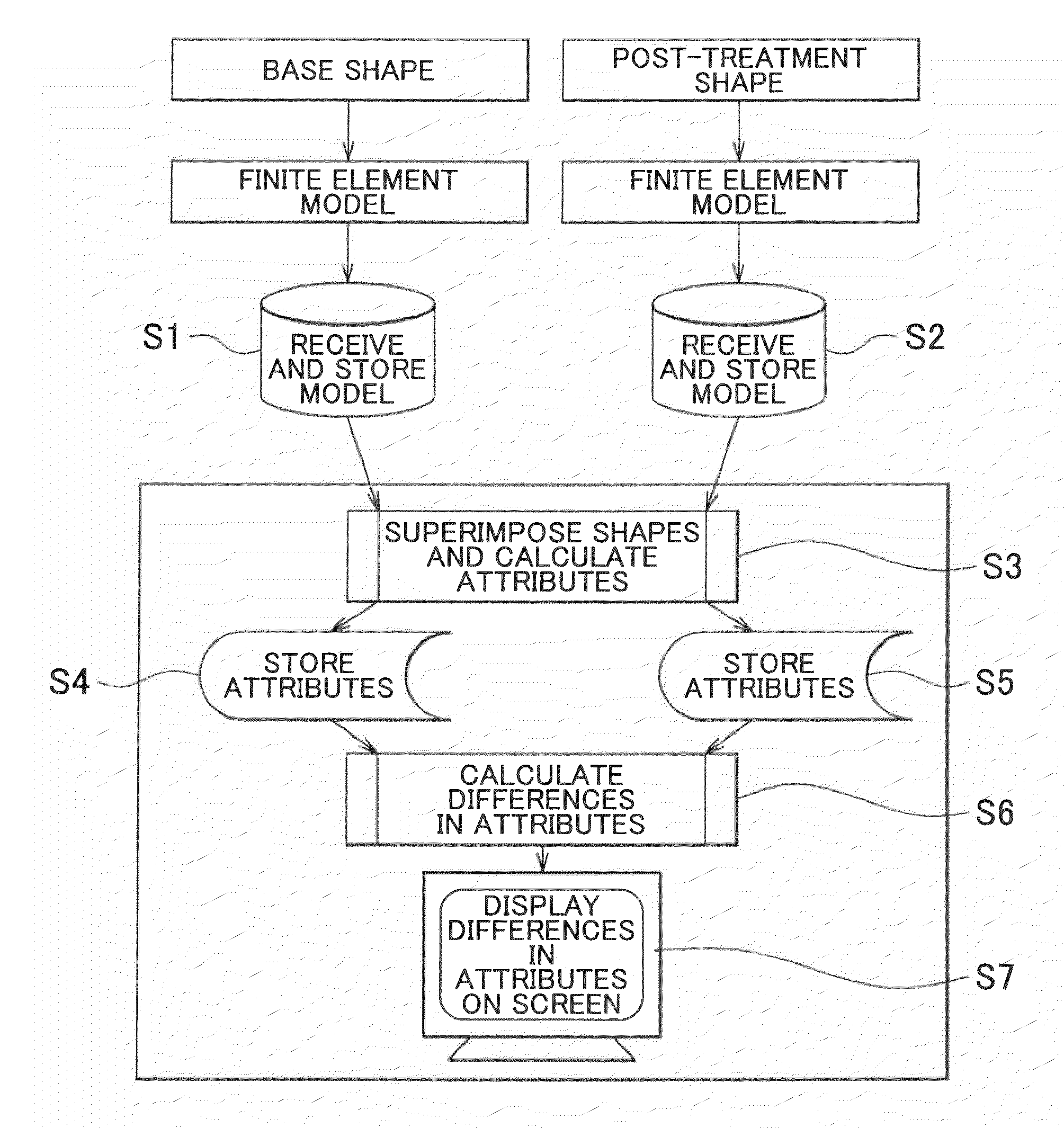
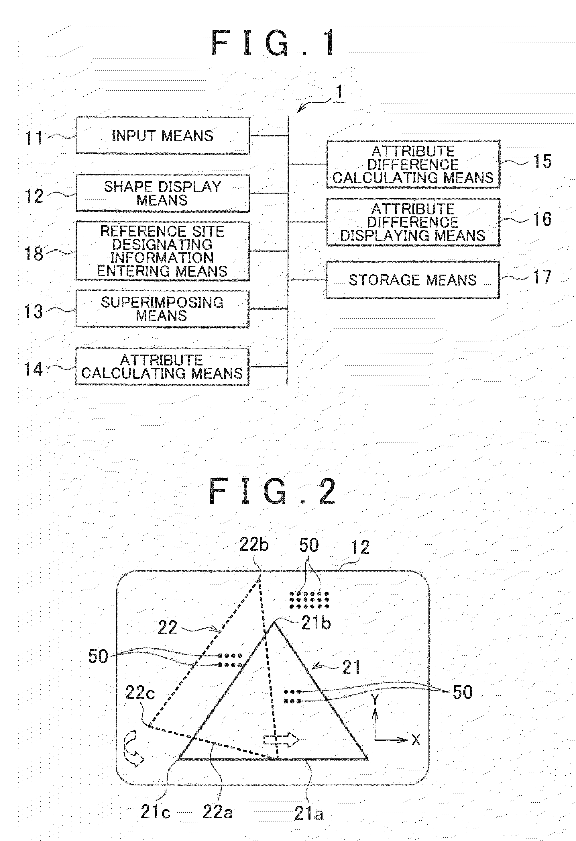
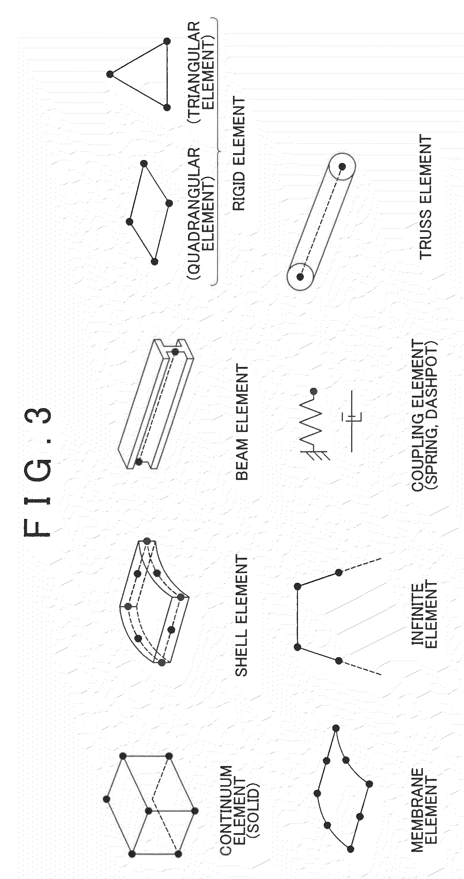
[0028]FIG. 1 illustrates a design support system 1 according to one embodiment of the invention. The design support system 1 includes an input means 11 for receiving shape data indicative of at least two, mutually different shapes, finite-element-model data indicative of a finite element model of each shape, and attribute data indicative of attributes set at nodes of an element, e.g., a triangular element in this embodiment, of the finite element model, and a shape display means 12 for displaying the two shapes on a screen. The design support system 1 further includes a reference site design...


PUM


Abstract

A design support system includes an input means for receiving shape data indicative of mutually different first and second shapes, finite element model data indicative of a finite element model for each shape, and attribute data indicative of an attribute at each node of the finite element model, a shape display means for displaying the shapes on a screen, a superimposing means for superimposing the shapes displayed on the screen, on each other, based on a reference site, an attribute calculating means for calculating the attributes at attribute calculation points set at predetermined positions on the screen, based on the attributes of the nodes, with respect to each of the superimposed shapes, and an attribute difference calculating means for calculating differences in the attributes of the nodes and the attribute calculation points of the respective shapes.

Description

INCORPORATION BY REFERENCE[0001]The disclosure of Japanese Patent Application No. 2007-178084 filed on Jul. 6, 2007, including the specification, drawings and abstract, is incorporated herein by reference in its entirety.BACKGROUND OF THE INVENTION[0002]1. Field of the Invention[0003]The invention relates to design support system, method and program, and more particularly to a design support technique for calculating and displaying differences in an attribute between different shapes.[0004]2. Description of the Related Art[0005]Techniques for calculating a difference in shape between different shapes are disclosed in, for example, Japanese Patent Application Publication No. 2005-266894 (JP-A-2005-266894) and Japanese Patent Application Publication No. 2005-208735 (JP-A-2005-208735). For example, a gear shape simulation method disclosed in JP-A-2005-208735 includes the steps of: obtaining a finite element model representing the shape of a toothed gear that has been subjected to heat ...

Claims


Application Information

Patent Timeline
Patent Type & Authority Applications(United States)
IPC IPC(8): G06F17/50G06F17/00G06F7/60
CPCG06T17/20
Inventor SAWADA, RYUSAKU
Owner TOYOTA JIDOSHA KK
Learn More