
Method and apparatus for diagnosing motor-operated valve

a motor-operated valve and diagnostic method technology, applied in mechanical instruments, weighing auxiliaries, instruments, etc., can solve problems such as the inability to diagnose a motor-operated valve, the inability to actuate the switch, and the wear or similar degradation of the disc spring in the spring cartridge, so as to achieve easy and quick diagnosis

Inactive Publication Date: 2009-01-15
SHIKOKU RES INST
View PDF4 Cites 0 Cited by
  • Summary
  • Abstract
  • Description
  • Claims
  • Application Information

AI Technical Summary

Benefits of technology

[0034]However, as described, some motor-operated valves develop hysteresis indicating that the elastic characteristics of the spring cartridge during valve closing is different from those during the valve opening depending on how the disc springs stay in the spring cartridge or on other reasons. In such a case, taking the elastic characteristics for the valve closing operation as that for the valve opening operation will reduce accuracy of the diagnosis.
[0168]In accordance with the motor-operated valve diagnostic apparatus of the invention as claimed in claim 27, constructed as described above, it is possible to determine the torque curve of the spring cartridge, based on the preload of the spring cartridge, for the corresponding specific condition of the spring cartridge, and by calibrating the original curve to the one thus determined, it is possible to achieve an easy and quick diagnosis on whether the torque-related characteristics of the motor-operated valve are appropriate or not.

Problems solved by technology

If the valve disc continues to be closed after it reaches the predetermined close position, damage may be caused to the valve disc, the interface between the worm and the link mechanism, or other parts of the valve disc.
However, the aforementioned disc springs in the spring cartridge may experience wear or similar degradation due to ageing or some other causes.
This can cause the torque switch to be actuated before the valve disc reaches a predetermined close position, or with an excessive margin for a specified allowable strength.
This in turn may prevent a motor-operated valve from operating properly in accordance with its characteristics.

Method used


Image

  • Method and apparatus for diagnosing motor-operated valve
  • Method and apparatus for diagnosing motor-operated valve
  • Method and apparatus for diagnosing motor-operated valve

Examples


embodiment 1

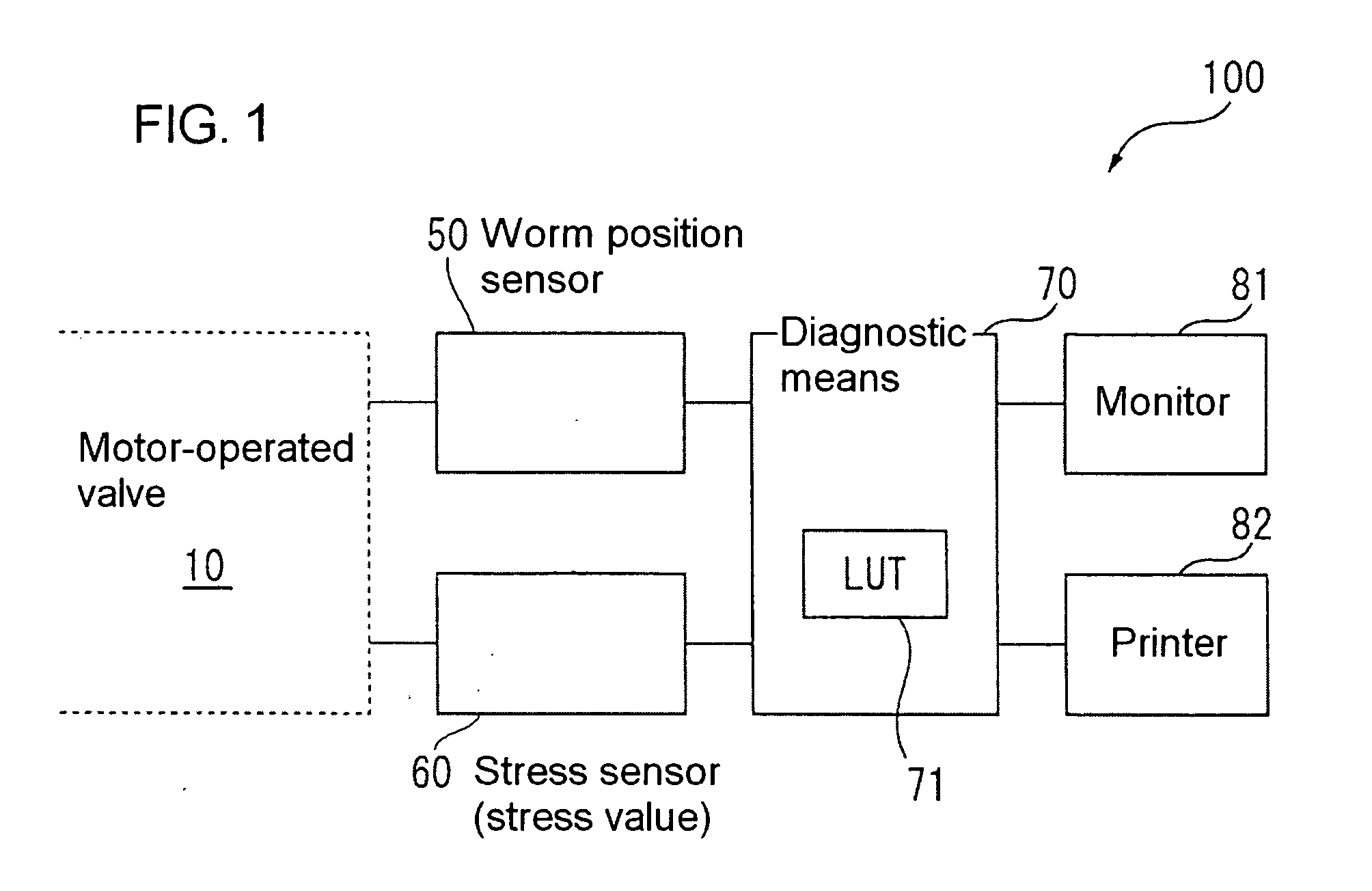
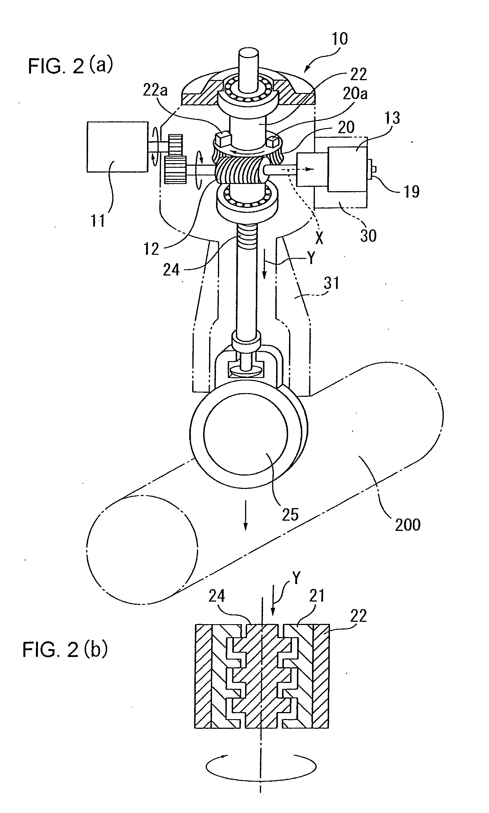
[0183]FIG. 1 is a block diagram showing one embodiment of the motor-operated valve diagnostic apparatus for practicing the motor-operated valve diagnostic method of this invention. FIG. 2 shows a motor-operated valve to which the motor-operated valve diagnostic apparatus 100 shown in FIG. 1 is to be applied.

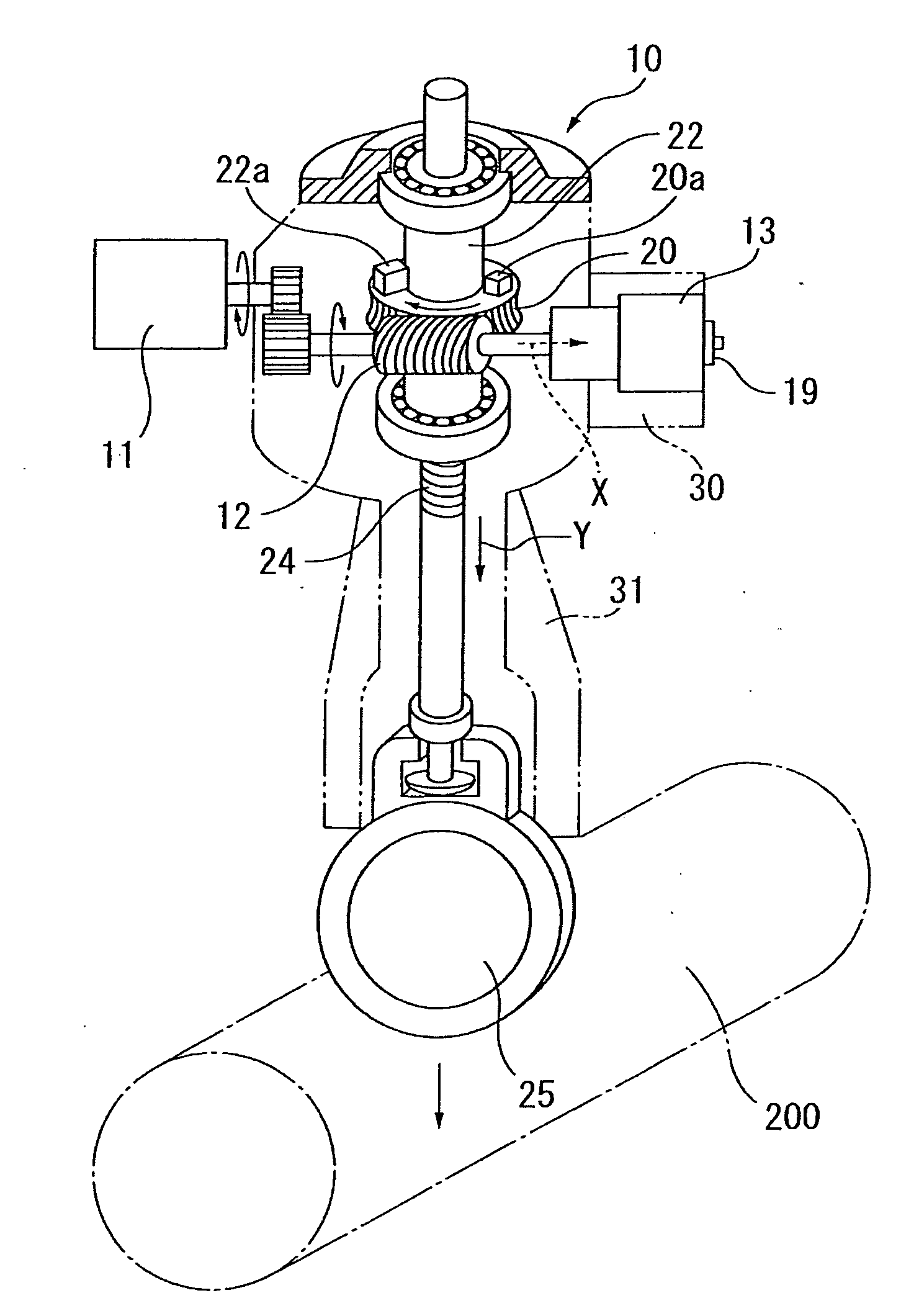
[0184]A motor-operated valve 10 of FIG. 1 is installed in a pipe 200 in a nuclear power plant, for example, and comprises a valve disc 25 for opening and closing a passage in the pipe 200, a worm 12 rotatably driven by motor power of the motor 11, a gear 20 constituting part of the link mechanism to open and close the valve disc 25, a drive sleeve 22, a stem nut 21 (see FIG. 2(b)) provided within the drive sleeve 22 and rotating together with the drive sleeve 22, a valve stem 24 engaging the stem nut 21, a spring cartridge 13 containing disc springs 15 (see FIG. 3) which expand or compress in response to reaction force acting on the worm 12 in the axial X direction from the link ...

embodiment 2

[0257]FIG. 7 is a block diagram showing another embodiment of the motor-operated valve diagnostic apparatus and method according to the invention.

[0258]The motor-operated valve diagnostic apparatus 100 shown in FIG. 7 is constructed exactly the same way as the motor-operated valve diagnostic apparatus 100 of Embodiment 1 shown in FIG. 1 except the following points. That is, the motor-operated valve diagnostic apparatus 100 comprises a stress sensor 61 which replaces the stress sensor 60 of the motor-operated valve diagnostic apparatus of Embodiment 1 shown in FIG. 1, the stress sensor 61 detecting the time when the valve disc 25 contacts the valve seat. The apparatus also has a timer 62 which measures an elapsed time t1 elapsed from the time Tk detected by the stress sensor 61 when the valve disc 25 contacts the valve seat to the time T1 when the displacement of the worm 12 in the X direction starts, the starting time of the worm 12 displacement corresponding to the starting time of...


PUM

PropertyMeasurementUnit
rotational driving forceaaaaaaaaaa
elastic characteristicsaaaaaaaaaa
displacementaaaaaaaaaa

Abstract

A diagnostic method and apparatus for diagnosing a motor-operated valve capable of continuously measuring a preload of a spring cartridge at low costs, with high accuracy, and with ease, so that the elastic characteristics of the spring cartridge may be easily calibrated in a simple manner. The method and apparatus is for diagnosing a motor-operated valve including a valve disc 25, a worm 12 rotatably driven by motor power, a link mechanism which opens and closes the valve disc 25 with the rotational driving force transmitted from the worm 12, and a spring cartridge 13 containing disc springs 15 which expand or compress in response to reaction force acting on the worm 12 in its axial direction from the link mechanism. The method and apparatus calibrates the torque curve representing the elastic characteristics the spring cartridge 13 based on the load corresponding to a specific compression condition of the spring cartridge 13, and based on the torque curve thus calibrated, produces a diagnosis of the motor-operated valve. Accordingly, an easy and quick diagnosis can be achieved on whether the torque-related characteristics of the motor-operated valve are appropriate or not.

Description

CROSS-REFERENCE TO RELATED APPLICATIONS[0001]This application is a division of U.S. application Ser. No. 10 / 545,608, filed Aug. 16, 2005, which is a filing under 35 USC 371 of PCT application PCT / JP2004 / 003072, filed Mar. 10, 2004 and claims priority of Japanese Patent Application No. 2003-062804 filed Mar. 10, 2003. The disclosures of all of the foregoing applications, inclusive of the specification, claims and drawings, are hereby incorporated by reference herein.TECHNICAL FIELD[0002]The present invention relates to a method and apparatus for diagnosing a motor-operated valve. More particularly, the invention relates to a method and apparatus which produces a torque-related diagnosis of a motor-operated valve. The diagnosis is produced by detecting a change in the preload of a spring cartridge containing disc springs and determining, based on the result of this detection, the elastic characteristics (torque curve) of the spring cartridge during a time when a motor-operated valve m...

Claims


Application Information

Patent Timeline
Patent Type & Authority Applications(United States)
IPC IPC(8): G01L25/00F16K37/00G01M99/00
CPCF16K37/0083
Inventor NOGAMI, TAKEKIYAMAGUCHI, SHIGEYA
Owner SHIKOKU RES INST
Learn More