Passive Thermal Management System

a passive thermal management and thermal management technology, applied in the field of thermal management, can solve the problems of not improving the heat transfer coefficient, the shape of the fin can be critical, and the heat sink is substantially ineffective, so as to achieve the effect of dissipating heat and dissipating hea

Inactive Publication Date: 2009-01-15
KONINKLIJKE PHILIPS ELECTRONICS NV
View PDF14 Cites 34 Cited by
  • Summary
  • Abstract
  • Description
  • Claims
  • Application Information

AI Technical Summary

Benefits of technology

[0010]An object of the present invention is to provide a passive thermal management system. In accordance with an aspect of the present invention, there is provided a passive thermal management system for dissipating heat generated by a heat source, the thermal management system comprising: one or more heat pipes each having a length, each heat pipe thermally connected to the heat s

Problems solved by technology

If the fan malfunctions, for example, air movement will likely be limited due to the spacing constraints, thus rendering the heat sink substantially ineffective.
This type of system typically requires larger spaces between fins associated with the heat sink, and the orientation and sh

Method used


Image

  • Passive Thermal Management System
  • Passive Thermal Management System
  • Passive Thermal Management System

Examples


example 1

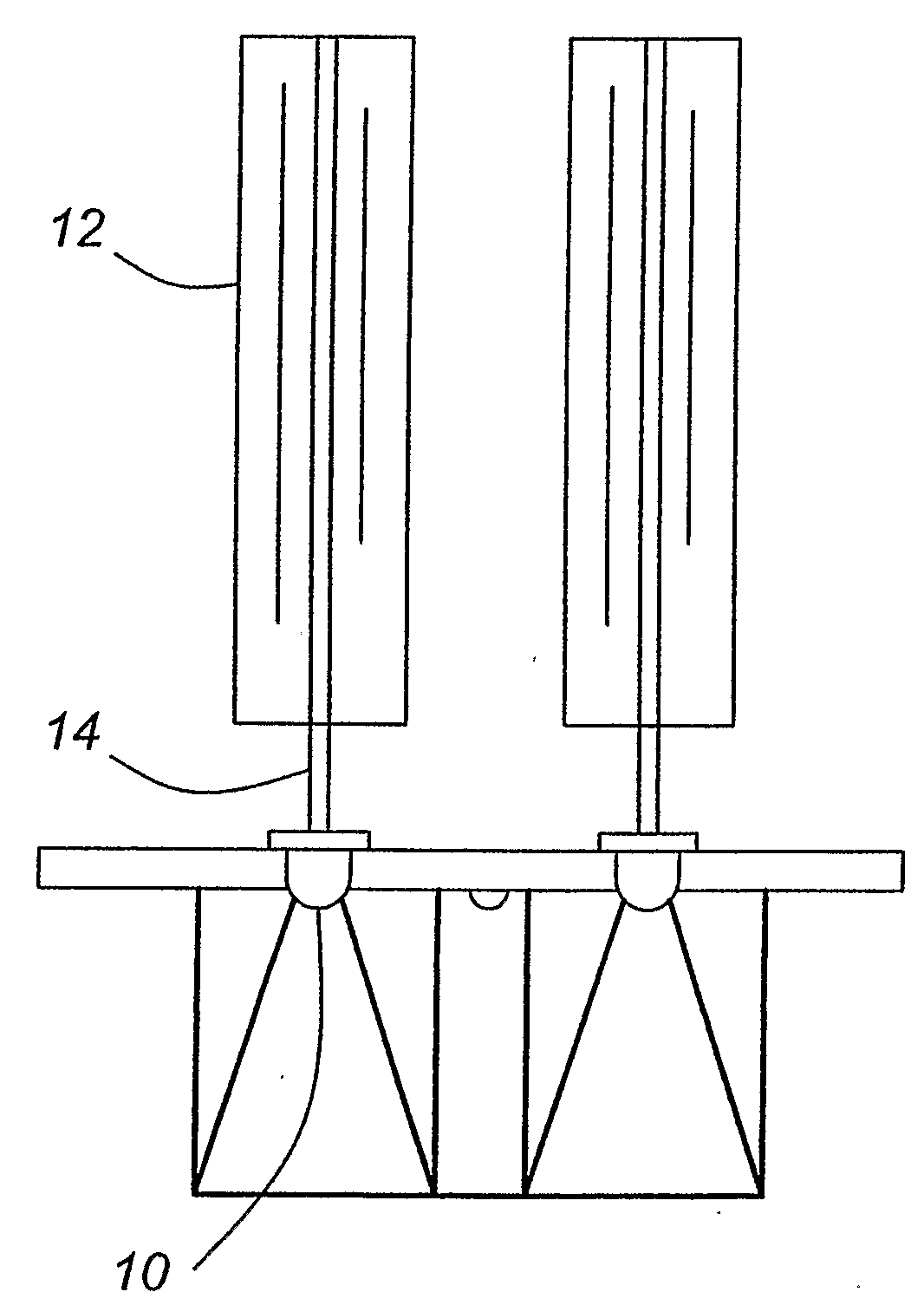
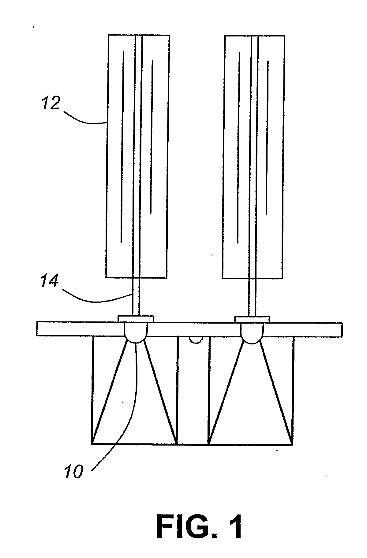
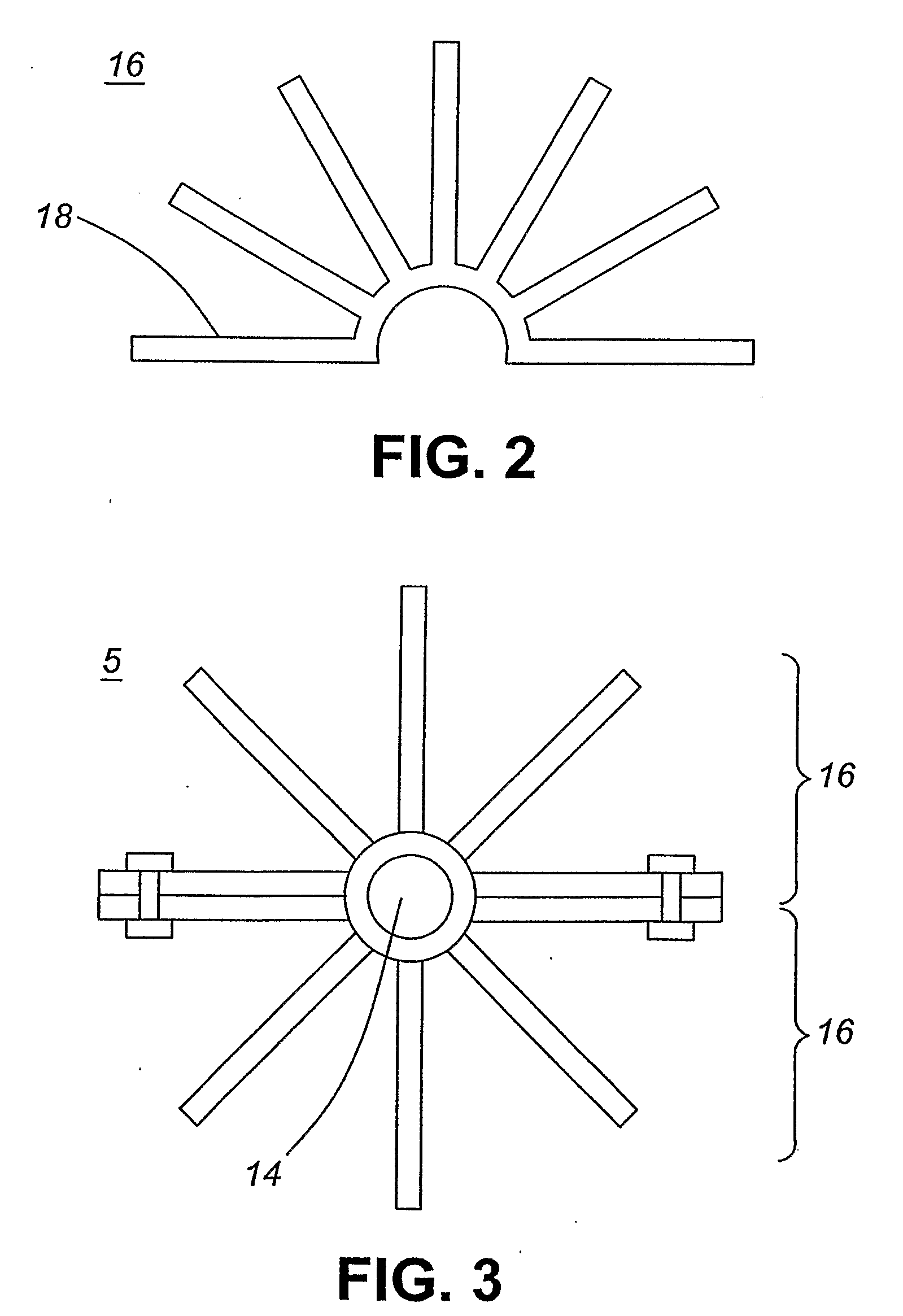
[0059]FIG. 1 illustrates a passive thermal management system according to one embodiment of the present invention. The thermal management system provides for the dissipation of heat that is generated by one or more light-emitting diodes 10 which are thermally coupled to the passive thermal management system, and more specifically heat pipe 14. For example, the thermal connection between the one or more light-emitting diodes and a heat pipe can be provided via substantially direct contact, through a LED package or via a thermally conductive substrate upon which the one or more light-emitting diodes are mounted. The thermal management system comprises heat pipes 14 which are thermally connected to a fin system 12 which is configured as a sleeve of fins. Each of the fins of the sleeve of fins are substantially aligned along the length of a heat pipe. The sleeve of fins functions as a heat sink and thereby passively transfers heat from a heat pipe to the surrounding environment, thereby...

example 2

[0064]In another embodiment of the present invention, the thermal management system comprises a fin system including two or more flat plate fins 34 that are thermally connected to one or more heat pipes 36 transverse to the length of each of heat pipes as illustrated in FIG. 7. These plate fins can be manufactured with one or more holes 38 therein for the insertion of a heat pipe therethrough as illustrated in FIG. 8.

[0065]In another embodiment, the plate fins can be manufactured with a plurality of holes 41 for the insertion of heat pipes and additionally include secondary holes 40 and 42 therein which can enable the passage of air therethrough, as shown in FIG. 9. The secondary holes 40 and 42 in adjacent plate fins can be aligned along the length of the heat pipes. Alternately the secondary holes in adjacent plate fins can be offset thereby providing a means for changing the direction of air movement along the length of the heat pipe, wherein the change in directional movement of...

example 3

[0066]FIG. 10A illustrates a configuration of the passive thermal management system for dissipating heat generated by a heat source located at end 45 according to another embodiment of the present invention. The thermal management system comprises one or more heat pipes 46 and a fin system comprising a plurality of curved fins 44. A single curved fin of the fin system is illustrated in FIG. 10B. The shape of the fins of the fin system is configured wherein the cool air enters into the passive thermal management system at a first velocity in a first direction 48 and is subsequently slowed, increasing thermal transfer thereto. The heated air thereafter exits the thermal management system at a second velocity in a second direction 50.

[0067]FIG. 11A illustrates a configuration of the passive thermal management system for dissipating heat generated by a heat source located at end 56 according to another embodiment of the present invention. The thermal management system comprises one or m...


PUM


Abstract

A traditional passive thermal management system can only be used effectively in a single orientation because it relies on the buoyancy of the heated air to create natural convection. A passive thermal management system is provided which includes means for transferring heat away from a heat source (10) in any orientation. The system comprises a heat pipe (14) which is thermally coupled to the heat source (10). The heat pipe (14) is capable of transferring heat away from the heat source (10), wherein this heat is transferred along the length of the heat pipe (14). Thermally coupled to the heat pipe (14) is a fin system (12), which provides a means for extraction of the heat from the heat pipe (14) and transfer of this heat to the environment thereby dissipating the heat generated at the heat source (10). The fin system (12) is configured to provide a desired level of heat transfer to the environment independent of the orientation of the thermal management system.

Description

FIELD OF THE INVENTION[0001]The present invention pertains to thermal management and in particular to a passive thermal management system.BACKGROUND[0002]Typical thermal management devices, especially those designed to incorporate heat pipes, are designed for one orientation to ensure proper airflow for efficient performance of the device. For example, heat sinks can be used to extract heat from a heat source and are designed based on the proximate airflow conditions and can vary greatly in shape and construction. For applications that allow the inclusion of a fan, the design of a heat sink can provide tightly spaced fins to reduce size, while enabling air to pass freely. If the fan malfunctions, for example, air movement will likely be limited due to the spacing constraints, thus rendering the heat sink substantially ineffective. Passive thermal management devices rely on buoyancy driven flow, or natural convection. Essentially, the air is heated by the heat sink, resulting in a re...

Claims


Application Information

Patent Timeline
IPC IPC(8): F28F7/00F28D15/00F21V29/15
CPCF21V29/004F28D15/0266F28D15/0275F28F1/14F28F1/20F21V29/773F28F1/32F28F1/34F21V29/006F21V29/713F21V29/77F28F1/24
Inventor SCHICK, PHILIPPEJAMES, DARYL
Owner KONINKLIJKE PHILIPS ELECTRONICS NV
Why Eureka
Try Eureka