Lubrication device and oil pan

a lubrication device and oil pan technology, which is applied in the direction of mechanical equipment, gearing details, machines/engines, etc., can solve the problems of insufficient and unstably restricted inflow of oil into the main chamber from the sub-chamber, acceleration of the progress of the warming-up operation, and the effect of the 2-chamber-type oil pan

Active Publication Date: 2009-01-15
TOYOTA JIDOSHA KK
View PDF9 Cites 26 Cited by
  • Summary
  • Abstract
  • Description
  • Claims
  • Application Information

AI Technical Summary

Benefits of technology

[0014]In a device having the 2-chamber-type oil pan described in Japanese Patent Application Laid-Open (kokal) No. 2003-222012 (Patent Document 1), even during the warming-up operation, the main chamber and the sub-chamber are communicated with each other through the first communication holes and the second communication holes. Accordingly, during the warming-up operation, the inflow of the oil into the main chamber from the sub-chamber is insufficiently and unstably restricted. Thus, the effect of the 2-chamber-type oil pan; i.e., the acceleration of the progress of the warming-up operation, is not necessarily sufficiently yielded.

Problems solved by technology

Accordingly, during the warming-up operation, the inflow of the oil into the main chamber from the sub-chamber is insufficiently and unstably restricted.
Thus, the effect of the 2-chamber-type oil pan; i.e., the acceleration of the progress of the warming-up operation, is not necessarily sufficiently yielded.
Therefore, in the device, the oil stored in the sub-chamber is unlikely to serve in circulation between the engine block and the oil pan.
For this reason, in the device, the oil stored in the oil pan (particularly, the oil continuously stored in the main chamber) can accelerate in deterioration.
Therefore, during the warming-up operation, the inflow of the oil into the main chamber from the sub-chamber can be reliably restricted.

Method used


Image

  • Lubrication device and oil pan
  • Lubrication device and oil pan
  • Lubrication device and oil pan

Examples


Embodiment Construction

[0137]An embodiment of the present invention (the best mode contemplated by the applicant at the time of filing the present application) will next be described with reference to the drawings.

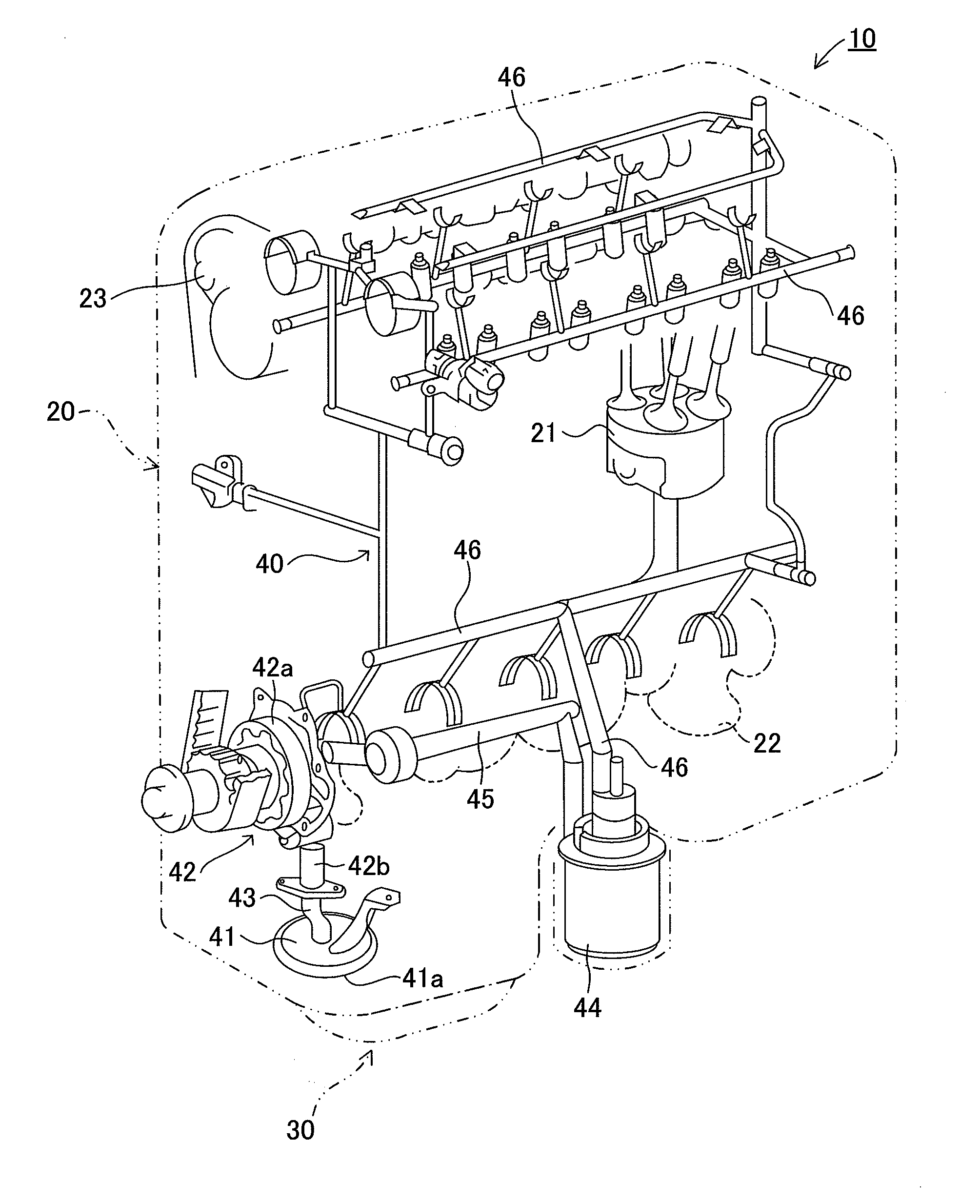
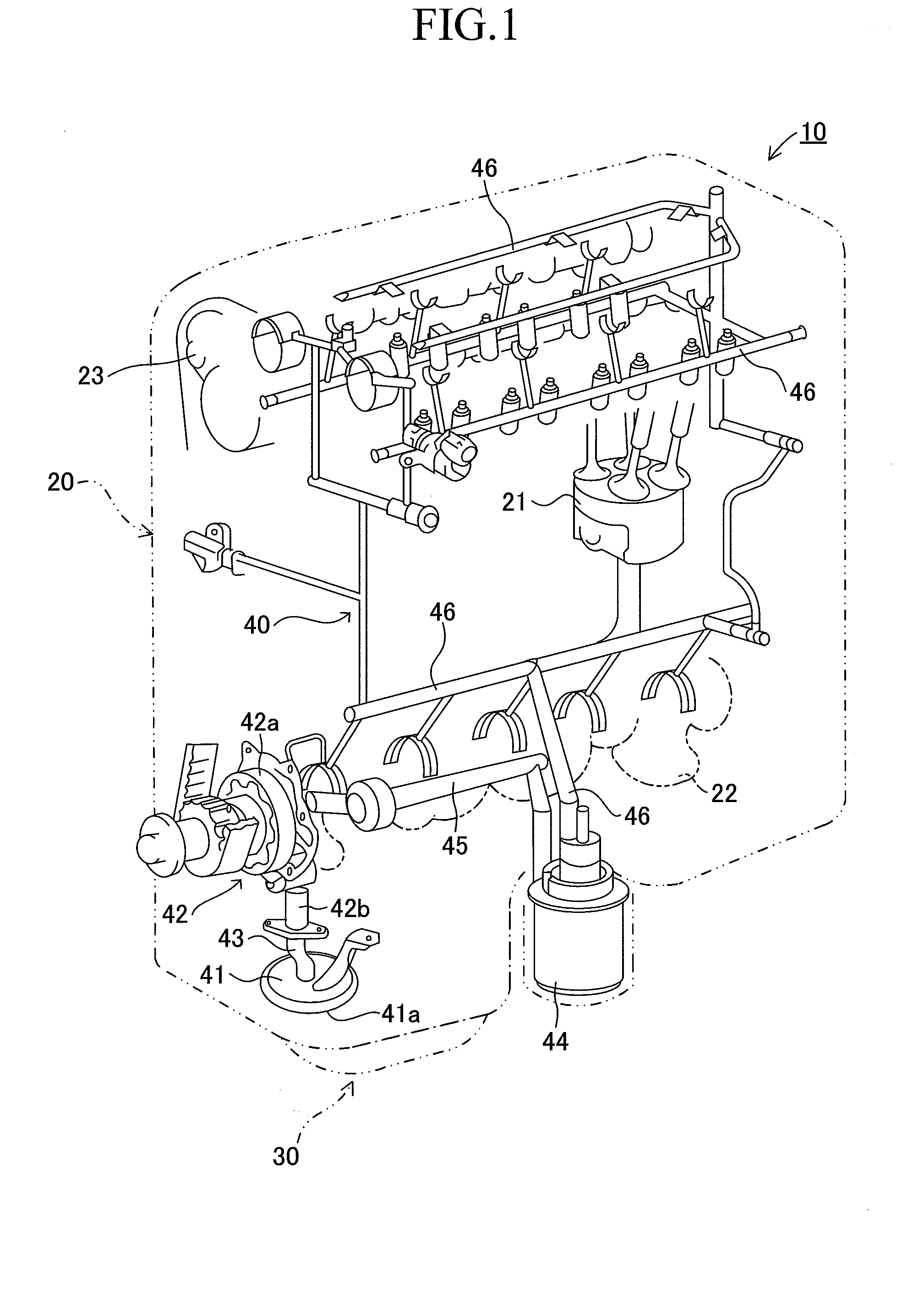
[0138]FIG. 1 is a schematic view of an engine 10, which is an embodiment of a lubrication device of the present invention. The engine 10 includes an engine block 20, an oil pan 30, and an oil feed section 40.

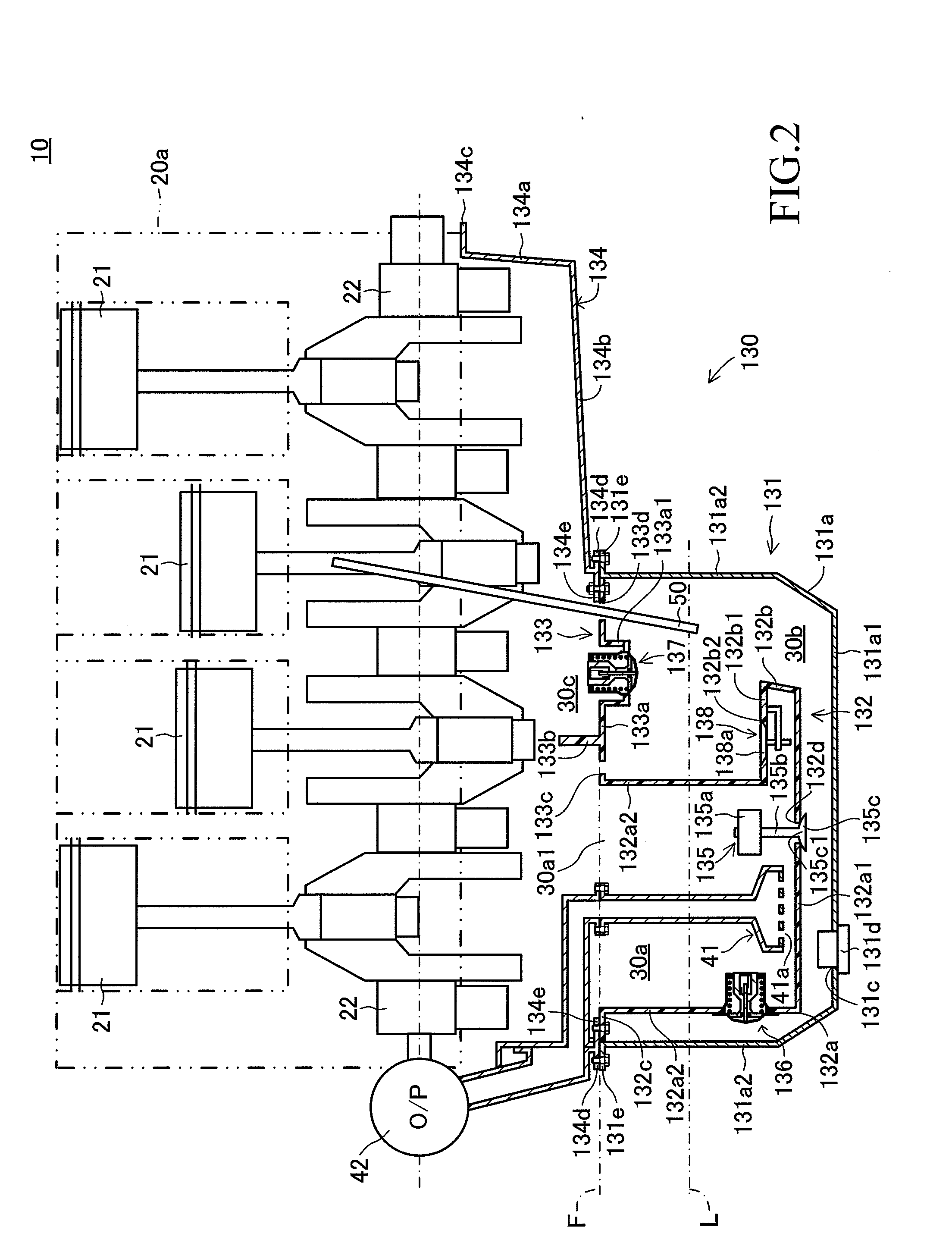
[0139]In an engine block 20, which serves as a mechanism-to-be-lubricated, a plurality of members-to-be-lubricated, such as pistons 21, a crankshaft 22, and a camshaft 23, are disposed. An oil pan 30 is connected to a lower end portion of the engine block 20. The oil pan 30 is configured to be able to store oil for lubrication of the interior of the engine block 20, in an inner space of the oil pan 30. The configuration of the oil pan 30 will be described in detail later.

[0140]The oil feed section 40 is configured, as described below, to be able to feed oil stored in the oil pan 30 to intern...


PUM


Abstract

An oil pan separator 132 is disposed so as to divide a space within an oil pan 130 into a first chamber 30a and a second chamber 30b. The oil pan separator 132 has a protrusion 132b formed at a low position in such a manner that a portion of the first chamber 30a protrudes into the second chamber 30b. A protrusion upper-plate 132b1, which serves as an upper end portion of the protrusion 132b, is provided with an oil feed valve 138, which is a one-way valve, for allowing substantially only outflow of oil from the first chamber 30a to the second chamber 30b.

Description

TECHNICAL FIELD[0001]The present invention relates to an oil pan capable of storing oil for lubricating a mechanism-to-be-lubricated (e.g., an engine block, an automatic transmission mechanism, or the like). The present invention also relates to a lubrication device (e.g., an engine, an automatic transmission, or the like) having the oil pan and configured to be able to feed the oil to the mechanism-to-be-lubricated.BACKGROUND ART[0002]Generally, a lubrication device of this kind is configured to be able to suck up the oil stored in the oil pan by means of an oil pump and to feed the sucked-up oil to members-to-be-lubricated (e.g., gears, cam shafts, cylinders, pistons, etc.) in the mechanism-to-be-lubricated. The lubrication device is configured to provide a lubricating action for the members-to-be-lubricated and such that the oil which has absorbed heat, such as frictional heat, from the members-to-be-lubricated returns into the oil pan from the mechanism-to-be-lubricated under th...

Claims


Application Information

Patent Timeline
Patent Type & Authority Applications(United States)
IPC IPC(8): F01M1/02F01M1/10F16N31/00F01M5/00F01M11/00F16H57/04
CPCF01M11/0004F01M2011/0037F01M2011/0041F16H57/0453F16H57/0447F16H57/0452F16H57/0404F01M5/00F01M11/04F01M11/12F02F7/00
Inventor YAMASHITA, YOSHIOKOBAYASHI, HIDEOARISAWA, KATUHIKOYAMADA, KENICHIHAYASHI, KUNIHIKOMORI, TAIITHI
Owner TOYOTA JIDOSHA KK
Why Eureka
Try Eureka