Sheet switch module

a switch module and switch technology, applied in the direction of contacts, legends, light and heating apparatus, etc., can solve the problems of loss of light, reduced light-guiding efficiency throughout the entire light-guiding sheet, and reduced light-guiding efficiency

Inactive Publication Date: 2009-01-15
CITIZEN ELECTRONICS CO LTD
View PDF7 Cites 21 Cited by
  • Summary
  • Abstract
  • Description
  • Claims
  • Application Information

AI Technical Summary

Benefits of technology

[0010]An object of the present invention is to provide a sheet switch module configured to arrange a light guiding plate in a horizontal (level) state,

Problems solved by technology

Consequently, there is a problem that efficiency of light guided from the light source 8 through the light guiding plate 12 to each key top 14 is reduced.
However, in the conventional technology disclosed in above-mentioned Japanese Patent Application Publication No. 2007-53063, the light-guiding sheet 16 te

Method used


Image

  • Sheet switch module
  • Sheet switch module
  • Sheet switch module

Examples


Embodiment Construction

[0028]Preferred embodiments of the present invention will be explained in detail hereinafter with reference to the accompanying drawings.

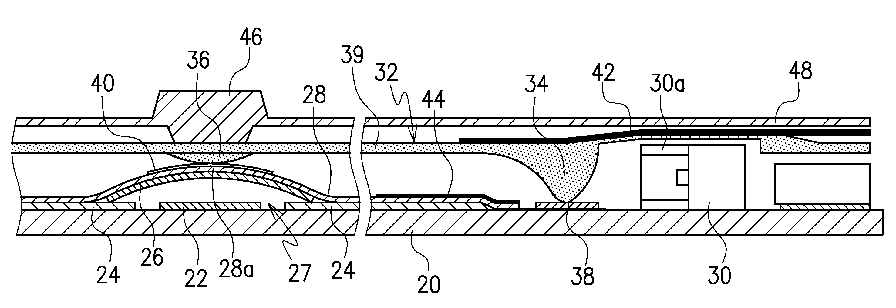
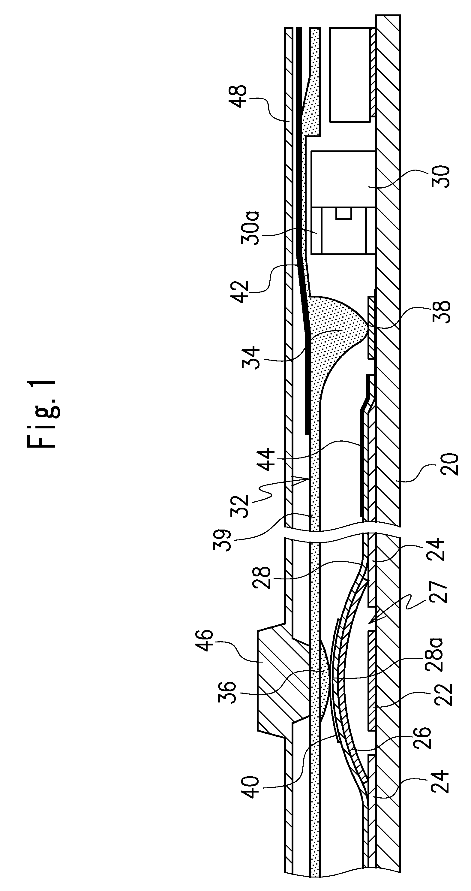
[0029]FIG. 1 illustrates a sheet switch module according to one embodiment of the present invention.

[0030]The sheet switch module in this embodiment includes a circuit board 20 formed by a flexible circuit board or the like and at least one switch 27 mounted on the circuit board 20. In the illustrated embodiment, a plurality of switches are provided on un upper surface of the circuit board 20. In this embodiment, each of the switches 27 includes a fixed contact 22 disposed on the upper surface of the circuit board 20 and a movable contact 26 which has a dome shape over the fixed contact 22 and has a peripheral edge disposed on and in contact with an electrode pattern 24 on the upper surface of the circuit board 20. The movable contact comprises, for example, a tact spring having a dome shape to achieve an electrical connection between the correspon...


PUM


Abstract

A sheet switch module includes a circuit board (20) provided with a fixed contact (22) thereon, a light source (30), a movable contact (26) to face the fixed contact (22), a sheet (28) to hold the movable contact (26) on the circuit board, a key top (46) disposed to face the movable contact and a light guiding plate (32) to guide light emitted from the light source (30) to the key top. The light-guiding plate (32) includes a light-receiving part (34) projecting toward an upper surface of the circuit board (20) and a light-guiding part (39). The light-guiding plate (32) is positioned in a substantially horizontal state supported by the light-receiving part (34) on the upper surface of the circuit board (20).

Description

CROSS-REFERENCE TO THE RELATED APPLICATION[0001]This application is based on and claims priority from Japanese Patent Application No. 2007-183817, filed on Jul. 13, 2007, the entire contents of which are hereby incorporated by reference.BACKGROUND OF THE INVENTION[0002]1. Field of the Invention[0003]The present invention relates to a sheet switch module used in small electronic devices or the like such as mobile phones.[0004]2. Description of the Related Art[0005]A conventional key switch used in small electronic devices or the like includes, as shown in FIG.5, a circuit board 2, a plurality of switches 10 provided on an upper surface of the circuit board 2, a plurality of light sources 8 mounted on the upper surface of the circuit board 2, and a light-guiding plate 12 disposed to cover the switches 10 (for reference, see Japanese Patent Application Publication No. 2007-53063, in particular FIG. 9).[0006]Each of the switches 10 includes a fixed contact 4 mounted on the upper surface...

Claims


Application Information

Patent Timeline
IPC IPC(8): H01H13/702
CPCH01H13/83H01H2205/016H01H2219/044H01H2221/07H01H2219/062H01H2221/002H01H2221/05H01H2219/056
Inventor AIHARA, KENSHIMIYASHITA, ISAO
Owner CITIZEN ELECTRONICS CO LTD
Why Eureka
Try Eureka