Container closure with deformable region in skirt to allow pivoting

a container and skirt technology, applied in the field of container closures, can solve problems such as potential tampering with container contents, and achieve the effects of facilitating finger insertion, facilitating initiation of pivoting of the second portion, and facilitating finger insertion

Inactive Publication Date: 2009-01-15
INNOVATIVE DESIGN
View PDF6 Cites 16 Cited by
  • Summary
  • Abstract
  • Description
  • Claims
  • Application Information

AI Technical Summary

Benefits of technology

[0017]In one form of the container, a container flange can be formed integrally with and to extend out from the container wall below the rim. The container flange typically functions to strengthen the container adjacent to the rim. Typically the length of the second portion is such that its distal end is positioned adjacent to the container flange when the closure is mounted to the container, typically in a close facing relationship (which can include abutment of the second portion distal end at the container flange). Locating the distal end of the second portion adjacent to the container flange can further assist with tamper proofing the arrangement. For example, an attempt to remove the closure from the container may require the insertion of an implement (eg. a blade) between the second portion distal end and the container flange, which may then be detected (eg. as a deformation of either of both of the second portion or flange).
[0018]However, in one embodiment the container flange is typically provided with one or more recesses adapted for receiving finger(s) of a user therein to facilitate finger insertion under and lifting of the second portion, thus facilitating initiation of pivoting of the second portion with respect to the first portion. In another embodiment the second portion can be provided with one or more recesses adapted for receiving finger(s) of a user therein to facilitate finger insertion under and lifting, and thus initiation of second portion pivoting.

Problems solved by technology

However, region deformation during pivoting can also indicate tampering with the closure, and hence potential tampering with container contents.

Method used


Image

  • Container closure with deformable region in skirt to allow pivoting
  • Container closure with deformable region in skirt to allow pivoting
  • Container closure with deformable region in skirt to allow pivoting

Examples


Embodiment Construction

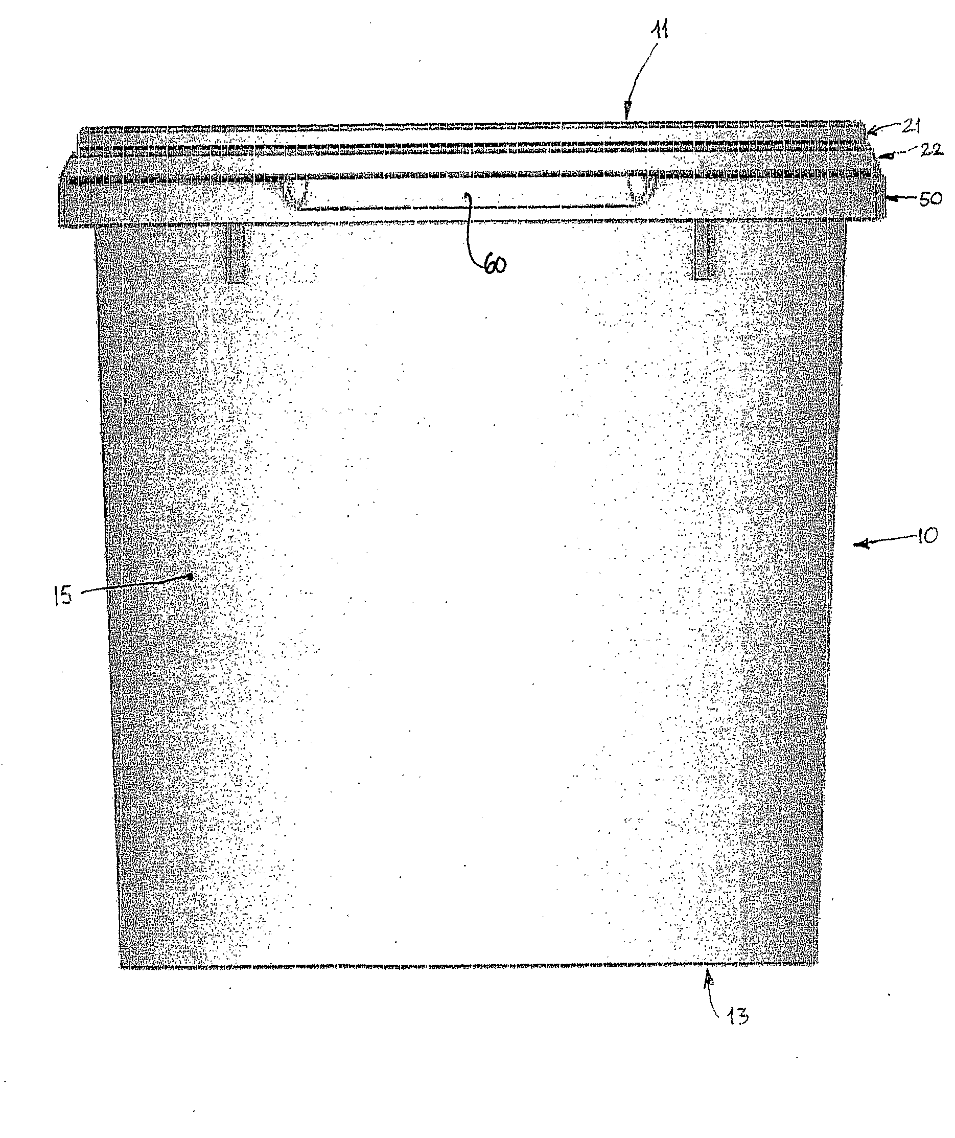
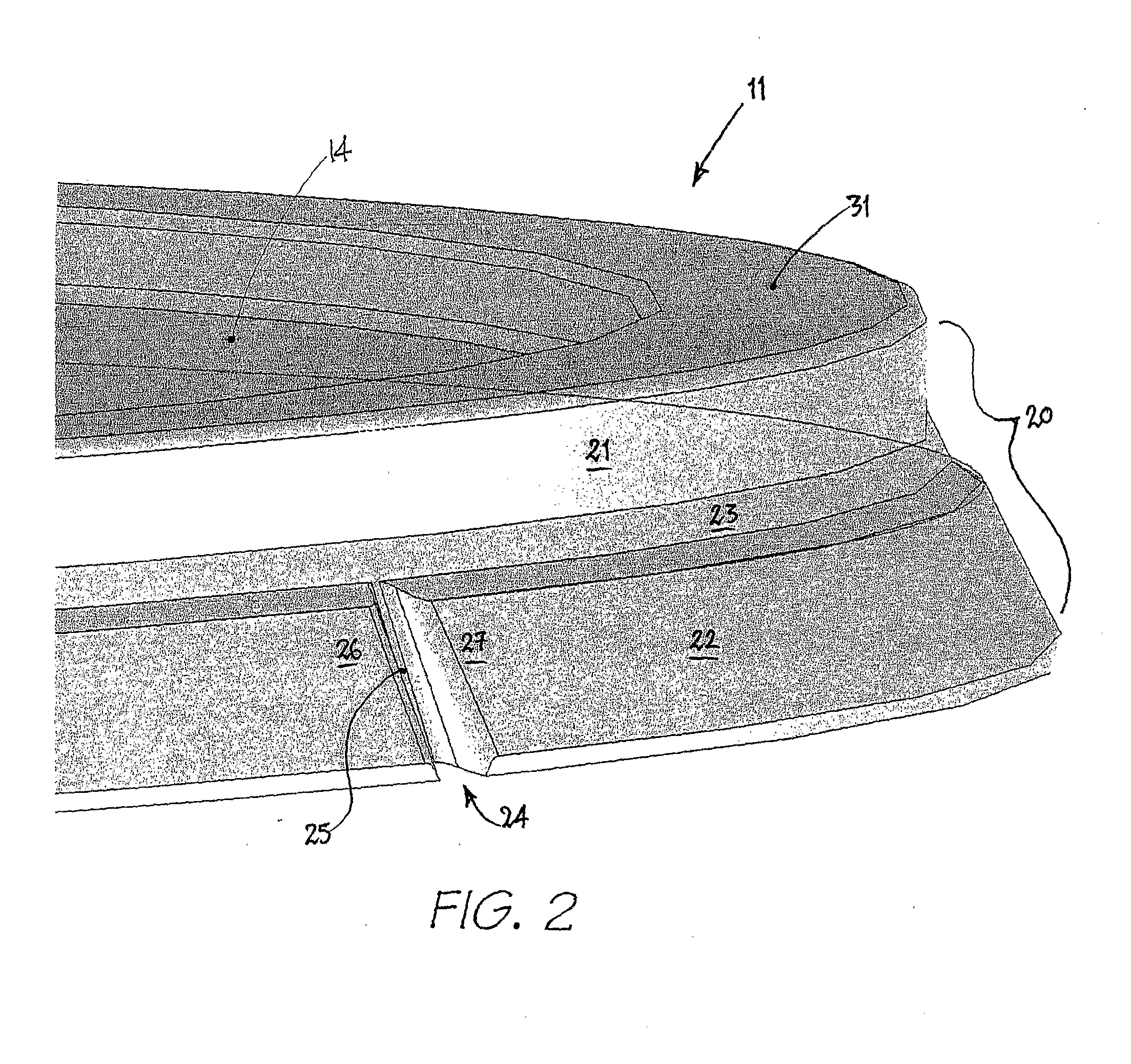
[0027]Referring to FIG. 1, an assembled container-closure arrangement is depicted comprising a container in the form of a pail 10, and a closure in the form of a lid 11. Whilst the arrangement is typically employed with a circular pail and lid as shown, the arrangement may be employed with square or rectangular pails and lids etc.

[0028]The pail and lid may each be moulded from polypropylene or high density polyethylene. The pail may be moulded in any desired size and may have a volumetric capacity in the order of eg. 0.5 to 20 litres. The pail may also be formed from a metal material. In addition, the lid-pail arrangements are suited to both tapered (FIG. 1) and straight-sided containers.

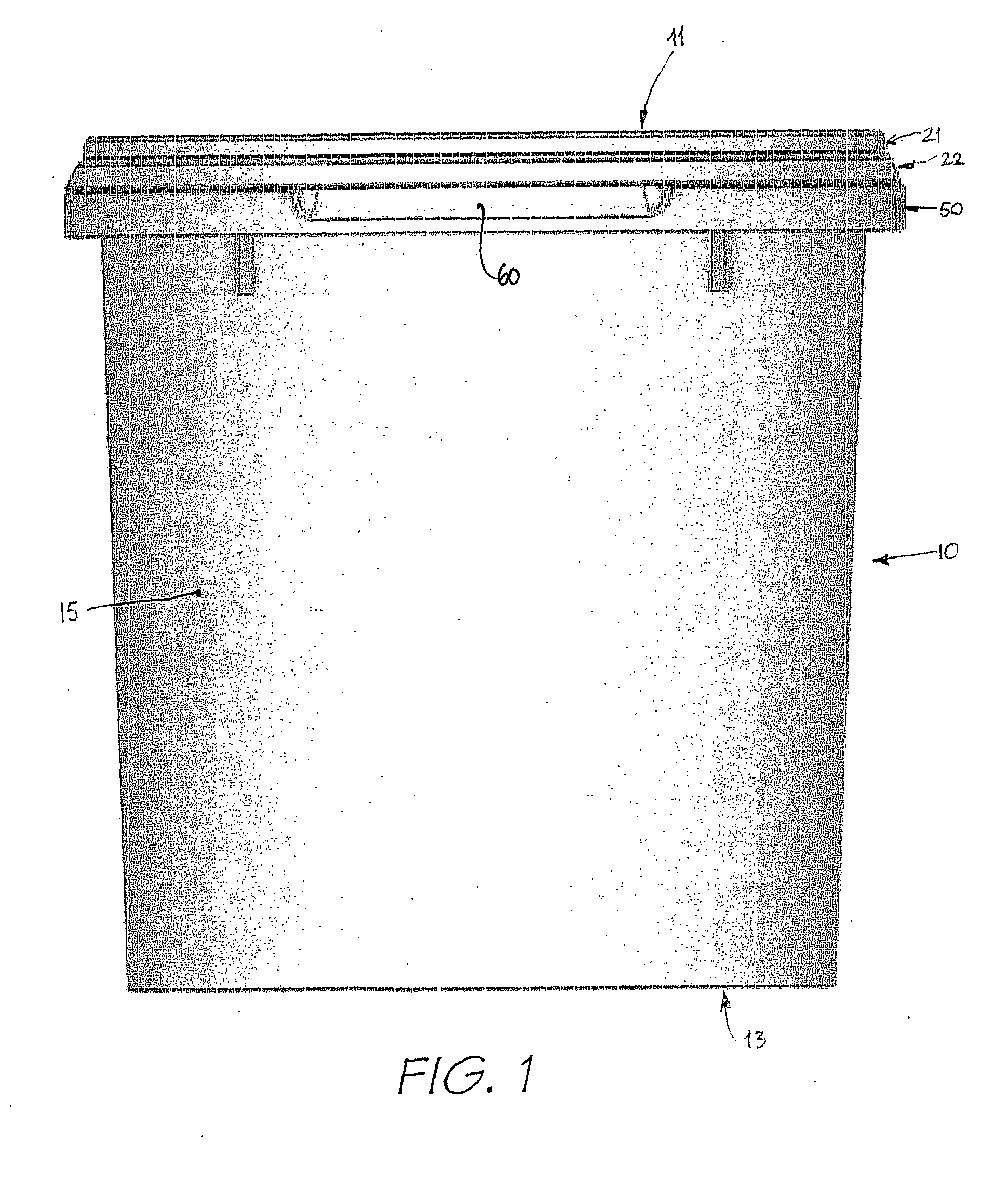
[0029]The pail 10 has a base 13 which is sized so that it can be located at a recess portion of the lid. In this regard, the recess portion includes a generally flat central region 14 (FIG. 2) whereby the base of an overlying pail can be positioned at region 14, so that a number of the pail-lid arra...


PUM


Abstract

A closure for a container is provided. The container may have a base and a peripheral wall. The peripheral wall may have a rim forming an upper margin of the peripheral wall and surrounding the opening of the container. The rim may have an external protrusion formed integrally with the rim and surrounding the rim. The closure may have an overlying closure portion adapted to overlie the opening of the container when the closure is mounted on the container. A skirt may be formed integrally with the overlying closure portion to surround the rim when the closure is mounted to the container. The skirt may include a first portion that is positionable adjacent to and to surround an external upper end of the rim, and may include a second portion that is connected to the first portion via a connection. The second portion may extend downwardly from the first portion to surround the rim below its upper end when the closure is mounted on the container. The second portion may include a first ledge which is designed for an interlocking engagement with the external protrusion of the rim. A deformable region may be provided in the second portion such that the deformable region may be deformed to facilitate pivoting of the second portion with respect to the first portion to disengage the first ledge from the external protrusion of the rim.

Description

REFERENCE TO RELATED APPLICATIONS[0001]This application is a national stage application under 35 USC 371 of International Application No. PCT / AU2006 / 000436, filed Mar. 31, 2006, which claims priority from an Australian patent application No. 2005901579, filed Mar. 31, 2005, the entire contents of which are incorporated herein by reference.BACKGROUND OF THE INVENTION[0002](i). Field of the Invention[0003]An improved closure for a container is disclosed wherein at least the closure (eg. in the form of a lid) is moulded from plastic. More particularly, the closure is adapted for reuse, but to also indicate tampering once initially removed.[0004](ii). Description of the Related Art[0005]Plastic and metal containers such as pails are used for holding chemicals including paints, solvents, oils, powders etc. It is desirable that the closure does not become detached from the container as a result of inadvertent dropping of the container and / or from shifting loads during handling, transport ...

Claims


Application Information

Patent Timeline
Patent Type & Authority Applications(United States)
IPC IPC(8): B65D39/00
CPCB44D3/127B65D43/0208B65D2543/00092B65D2543/00296B65D2543/00796B65D2543/00629B65D2543/00685B65D2543/0074B65D2543/00518
Inventor WOINARSKI, DAVID ALEXANDER
Owner INNOVATIVE DESIGN
Why Eureka
Try Eureka