Welding wire guide ring

Active Publication Date: 2009-01-15
LINCOLN GLOBAL INC
View PDF32 Cites 27 Cited by
  • Summary
  • Abstract
  • Description
  • Claims
  • Application Information

AI Technical Summary

Benefits of technology

[0010]In still another aspect of the embodiments of the present invention, the aperture is spaced apart from a plane crossing through the inner peripheral edge by a distance D, wherein the distance D is substantially in the range from 1 to 5 inches an

Problems solved by technology

However, dispensing wire from coils presents the problem of unwinding the wire uniformly without intertwining or forming knots, which can lead to defects or breaks in the wire resulting in costly downtime.
In

Method used


Image

  • Welding wire guide ring
  • Welding wire guide ring
  • Welding wire guide ring

Examples


Embodiment Construction

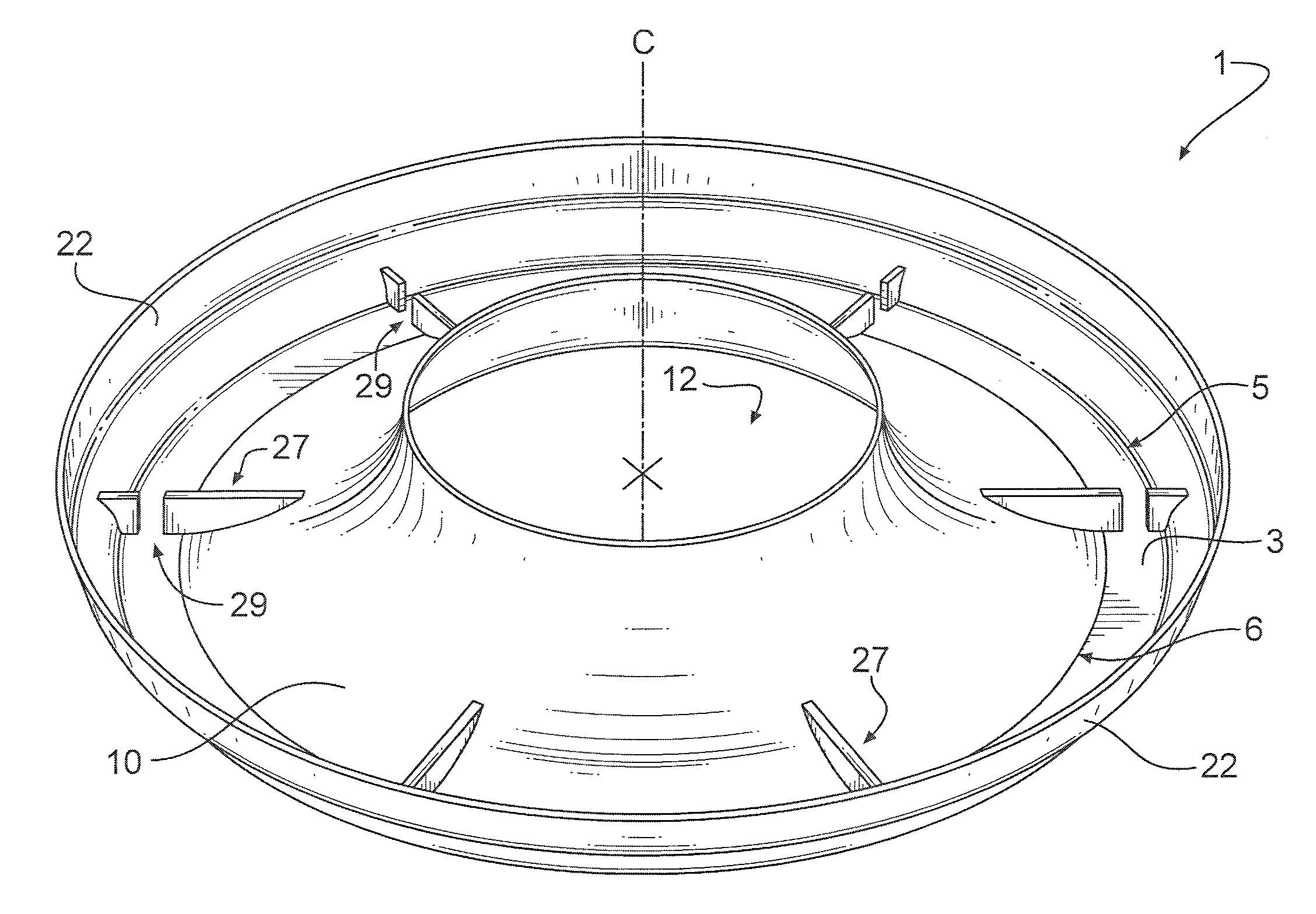
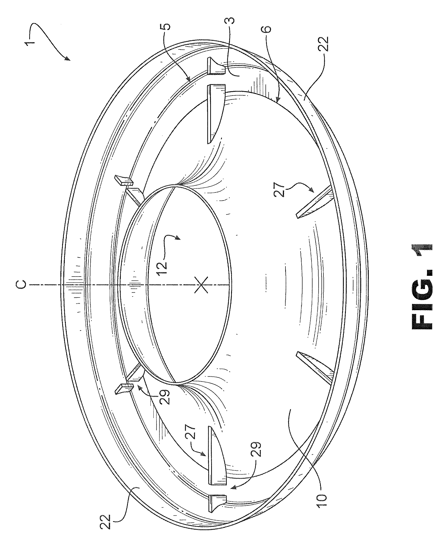
[0018]Referring now to the drawings wherein the showings are for purposes of illustrating embodiments of the invention only and not for purposes of limiting the same, FIG. 1 shows a wire guiding device depicted generally at 1. The wire guiding device 1 may include a generally planar bottom referred to as the base or base portion 3. The base portion 3 may have an annular configuration defining an outer peripheral edge 5. The base portion 3 may further include an inner peripheral edge 6 lying in close proximity to or substantially in the same plane as the outer peripheral edge 5. While the outer peripheral edge 5 of the base portion 3 is described herein as being circular in configuration, persons of ordinary skill in the art will readily understand the application of other geometric shapes to the embodiments of the present invention. The wire guiding device 1 may also include a guide portion or wire guide portion 10. The wire guide portion 10 may extend inward from the inner peripher...


PUM

PropertyMeasurementUnit
Angleaaaaaaaaaa
Weightaaaaaaaaaa
Weightaaaaaaaaaa

Abstract

A wire guiding device includes a base and a guide portion for streamlining the flow of coiled wire from a storage container. Side walls may be included to bridge the distance between the device and the storage container to prevent wire from rising upward around the outside of the wire guiding device. As the amount of wire in the bin decreases, the wire guiding device will float downward maintaining constant downward pressure on the coil of wire. Wire in the storage container will therefore be drawn out in a smooth manner limiting or substantially preventing tangles.

Description

TECHNICAL FIELD[0001]The present invention pertains to a wire guiding device for dispensing wire, and more particularly, to a welding wire guide ring used to dispense wire from a drum or container.BACKGROUND OF THE INVENTION[0002]Wire is frequently packaged and stored in drums for delivery to an end user. In particular, wire such as that used for welding or soldering, is wound in coils as it is placed in the drums. Once shipped to the end user, the wire is dispensed from the container for use in numerous processes. In many instances, the wire is left in the container and metered out as needed without removing the entire coil. Suppliers frequently incorporate a twist in the wire as it is fed into the drum, which helps the wire emerge without rotating as it is drawn back out.[0003]However, dispensing wire from coils presents the problem of unwinding the wire uniformly without intertwining or forming knots, which can lead to defects or breaks in the wire resulting in costly downtime. T...

Claims


Application Information

Patent Timeline
IPC IPC(8): B65H57/18
CPCB23K9/1333B65H57/18B65H49/08B23K9/133
Inventor BENDER, RAYMONDBARTON, DAVIDMATTHEWS, HERB
Owner LINCOLN GLOBAL INC
Why Eureka
Try Eureka