Assembling Structure for Electronic Module

a technology of electronic modules and assembly structures, applied in the direction of electrical apparatus construction details, electrical apparatus casings/cabinets/drawers, instruments, etc., can solve the problems of user fingers being slashed, inconvenient and dangerous, and the space in the housing is very crowded, so as to improve the inconvenience of assembly

Inactive Publication Date: 2009-01-15
FIRST INTERNATIONAL COMPUTER
View PDF29 Cites 14 Cited by
  • Summary
  • Abstract
  • Description
  • Claims
  • Application Information

AI Technical Summary

Benefits of technology

[0005]According to the above drawbacks, the present invention provides an assembling structure for electronic module to improve the assembly inconvenience due to the space restriction.
[0006]The primary objective of the present invention is to provide an assembling structure for electronic module comprising a case and a side frame. The characteristic of the present invention is the case fixed on the base frame of the assembling structure by two front pivots and the case is pivoted thereon, the side frame is adjacent to the case. Furthermore, the case and the side frame include a plurality of locking holes respectively, wherein the locking holes of the case are corresponding to the locking holes of the side frame. Additionally, the side frame further includes a locking controller with a first latch and a second latch, each corresponding to locking holes of the case and side frame, thereby locking the case at a horizontal and oblique position. By this way, it is more convenient to assemble electronic modules without space restrictions of prior art.
[0008]Furthermore, the case further includes a plurality of auxiliary positioning convex disposed on the side wall adjacent to the side frame, and the side frame also includes a plurality of auxiliary positioning concave set correspondingly to the auxiliary positioning convexs. By means of the convexs and concaves, the case is assisted to be positioned multistagely between the horizontal and oblique position. Therefore, the auxiliary positioning function is provided to keep the case away from rotating randomly and clapping suddenly to avoid dangers. Moreover, the auxiliary positioning convexs and concaves are on the sites that are corresponding and exchangeable mutually, that is to say, the auxiliary positioning convexs could be set on the case and the auxiliary positioning concaves could be set on the side frame, alternatively, the auxiliary positioning convexs could be set on the side frame and the auxiliary positioning concaves could be set on the case. In brief, the auxiliary positioning convexs and concaves are matched mutually to provide the auxiliary positioning function to prevent dangers no matter which form is adopted.

Problems solved by technology

Besides, other related device, such as a power supply, disposed on the housing, also occupies some space.
Thus, the space in the housing is very crowded.
Users' fingers may be slashed if the users stretched hands into the housing for assembly and repair.
So it is very inconvenient and dangerous.
Consequently the assembling structure with immoveable shelves and crowded inner space in the housing is really inconvenient to users.
As such, it is relatively inconvenient to mount or dismount the peripheral devices in the computer housing through tightening or loosening of the screw means.
Although the invention is provided for mounting the peripheral devices in the computer housing without screw means, the inconvenience resulting from the space restriction and immoveable shelves is not overcame yet, and the problem is still exists.

Method used


Image

  • Assembling Structure for Electronic Module
  • Assembling Structure for Electronic Module
  • Assembling Structure for Electronic Module

Examples


Embodiment Construction

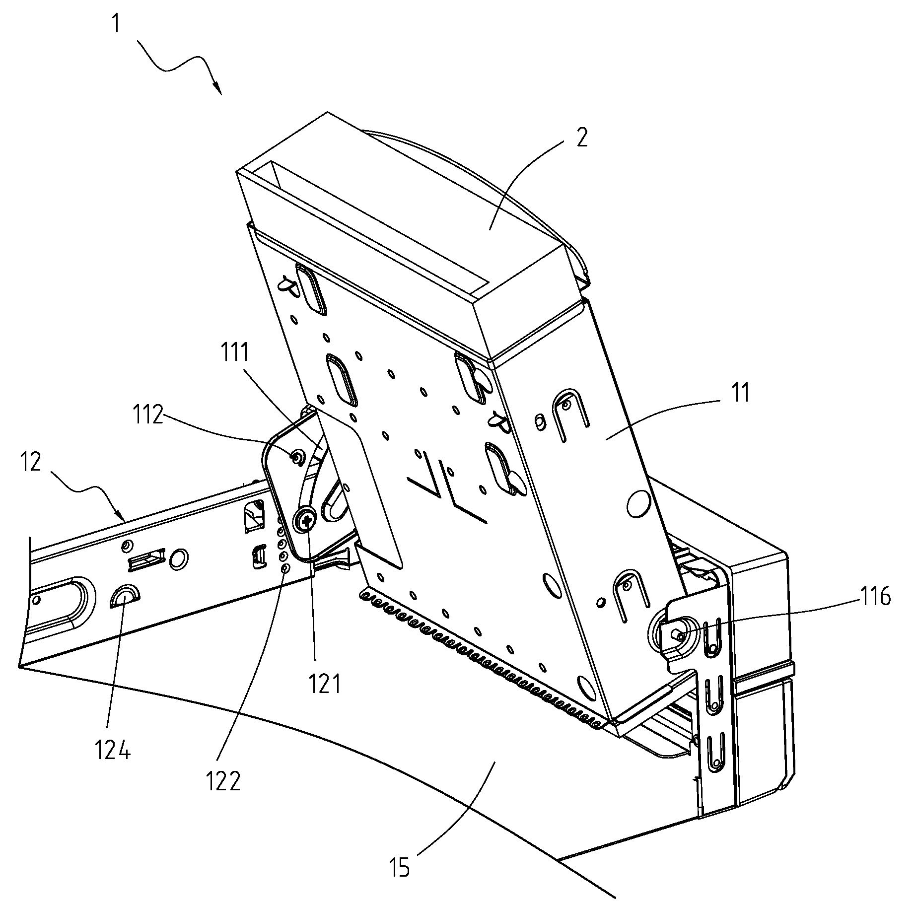
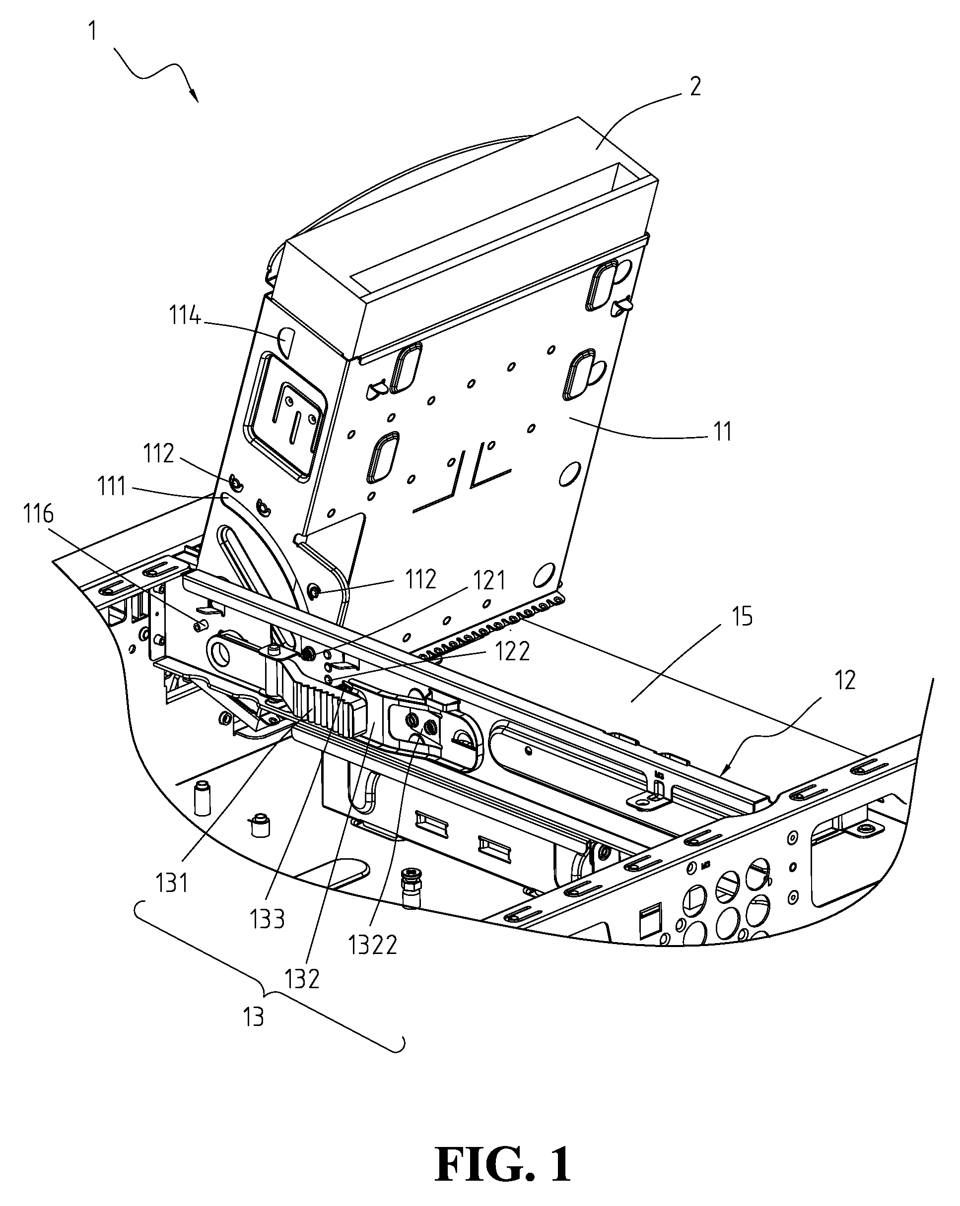
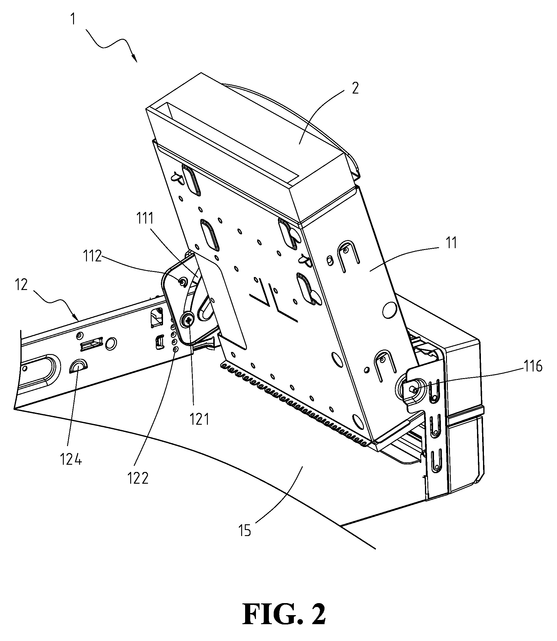
[0018]Referring to FIG. 1, FIG. 3, FIGS. 5a and 5b to illustrate the left view, the exploded view, and the horizontal and oblique positions of the case of the present invention, respectively. The assembling structure for electronic module 1 comprises a case 11 and a side frame 12 and the characteristic is that the case 11 fixed on the base frame 15 of the assembling structure 1 by two front pivots 116 and the case 11 pivoted thereon. In addition, the side frame 12 is disposed adjacent to the case 11. Furthermore, the case 11 and the side frame 12 include a plurality of locking hole respectively, wherein the locking holes of the case 11 are corresponding to the locking holes of the side frame 12. In the preferred embodiment, the locking holes are the first locking hole 113, the second locking hole 113′, the third locking hole 114, the fourth locking hole 123, and the fifth locking hole 124. Besides, the side frame 12 further includes a locking controller 13 with a first latch 131 and...


PUM


Abstract

The assembling structure for electronic module comprise a case and a side frame, the characteristic is the case fixed on the base frame of the assembling structure by two front pivots and the case pivoted thereon. Besides, the side frame is installed adjacent to the case. In addition, the case and the side frame respectively include a plurality of locking holes, the side frame further including a locking controller with a first latch and a second latch corresponding to the locking holes, thereby locking the case at a horizontal and oblique position.

Description

FIELD OF THE INVENTION[0001]The present invention relates to an assembling structure, and more particularly, to an assembling structure for electronic module.BACKGROUND OF THE INVENTION[0002]With the increasing demands for IT products, the related technologies and products are developed on large scale. For examples, computer products and multimedia equipments are developed with rapid growth and progress. However, the peripheral device, such as an optical disk drive, hard disk drive or floppy disk drive, is usually installed in immoveable shelves in a metal housing. Besides, other related device, such as a power supply, disposed on the housing, also occupies some space. Thus, the space in the housing is very crowded.[0003]Additionally, the housing and the shelves are made of metal materials and have keen edges and corners. Users' fingers may be slashed if the users stretched hands into the housing for assembly and repair. So it is very inconvenient and dangerous. Furthermore, the per...

Claims


Application Information

Patent Timeline
Patent Type & Authority Applications(United States)
IPC IPC(8): H05K5/00
CPCG11B33/123
Inventor CHEN, CHIANG-KO
Owner FIRST INTERNATIONAL COMPUTER
Why Eureka
Try Eureka