Acceleration sensor, electronic device comprising the same, and acceleration measuring method

a sensor and acceleration technology, applied in the field of acceleration sensors, can solve the problems of difficult acceleration detection with high precision, inability to reduce the size of the device, and complicated structure of the wiring, so as to improve the sensitivity of acceleration detection and simplify the structure. , the effect of simple structur

Active Publication Date: 2007-02-01
SAE MAGNETICS (HK) LTD
View PDF6 Cites 15 Cited by
  • Summary
  • Abstract
  • Description
  • Claims
  • Application Information

AI Technical Summary

Benefits of technology

[0007] The object of the present invention therefore is to improve the inconveniences of the above-described conventional case and, more particularly, to provide an acceleration sensor that is capable of detecting the acceleration with high precision as well as capable of reducing the size and cost by the simple structure.

Problems solved by technology

Thus, the structure may be complicated by the wirings.
Further, the distortion sensor elements are mounted to the supporting member so that the size thereof cannot be reduced.
Furthermore, it has been an issue that displacement of the spring is obstructed so that it becomes difficult to detect acceleration with high precision since the distortion sensor element is mounted or built in the spring part of the supporting member internally.

Method used


Image

  • Acceleration sensor, electronic device comprising the same, and acceleration measuring method
  • Acceleration sensor, electronic device comprising the same, and acceleration measuring method
  • Acceleration sensor, electronic device comprising the same, and acceleration measuring method

Examples


first embodiment

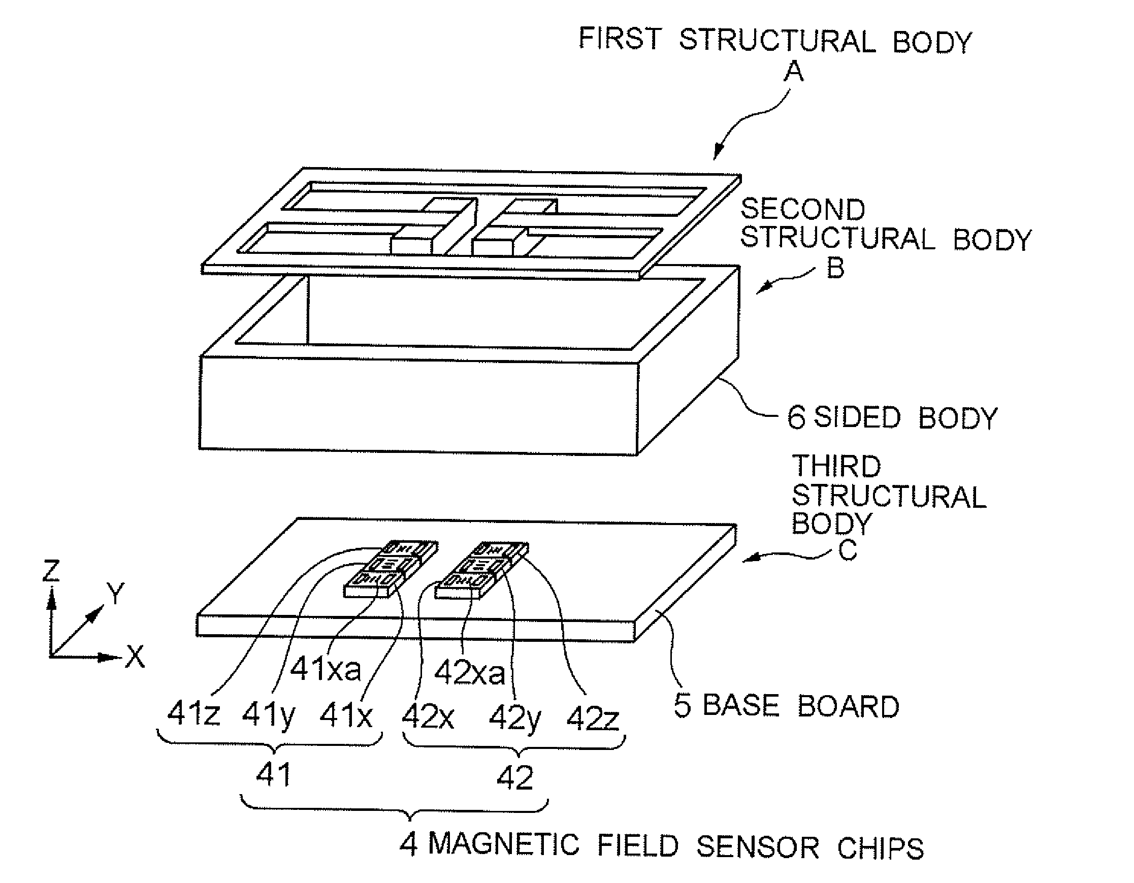
[0085] A first embodiment of the present invention will be described by referring to FIG. 1-FIG. 10. FIG. 1 and FIG. 2 are illustrations for showing the structure of an acceleration sensor. FIG. 2-FIG. 8 are illustrations for describing the principle and method for measuring the acceleration. FIG. 9 is a schematic diagram for showing the structure of the acceleration sensor. FIG. 10 is an illustration for showing a modification example of the structure of the acceleration sensor.

Structure

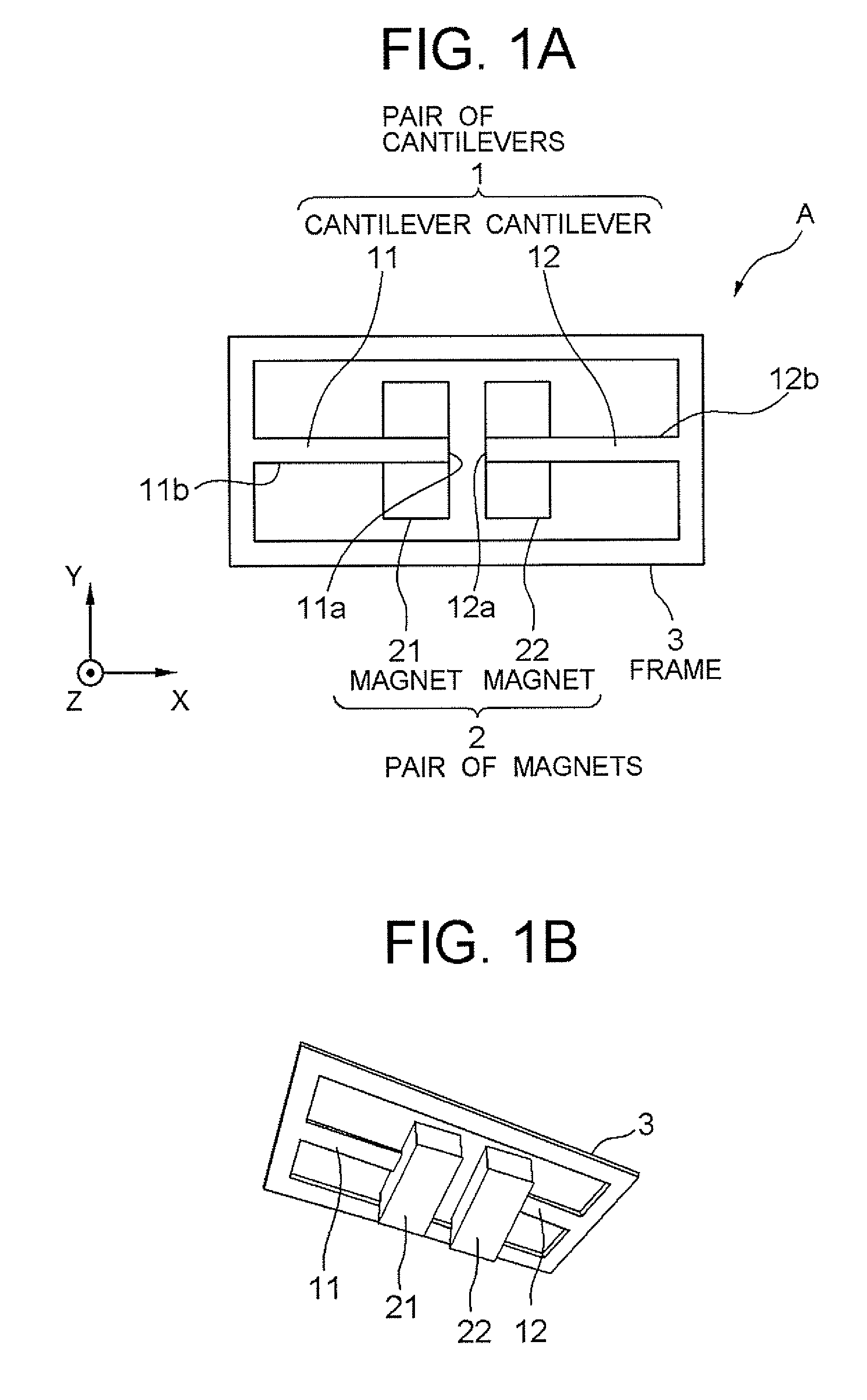
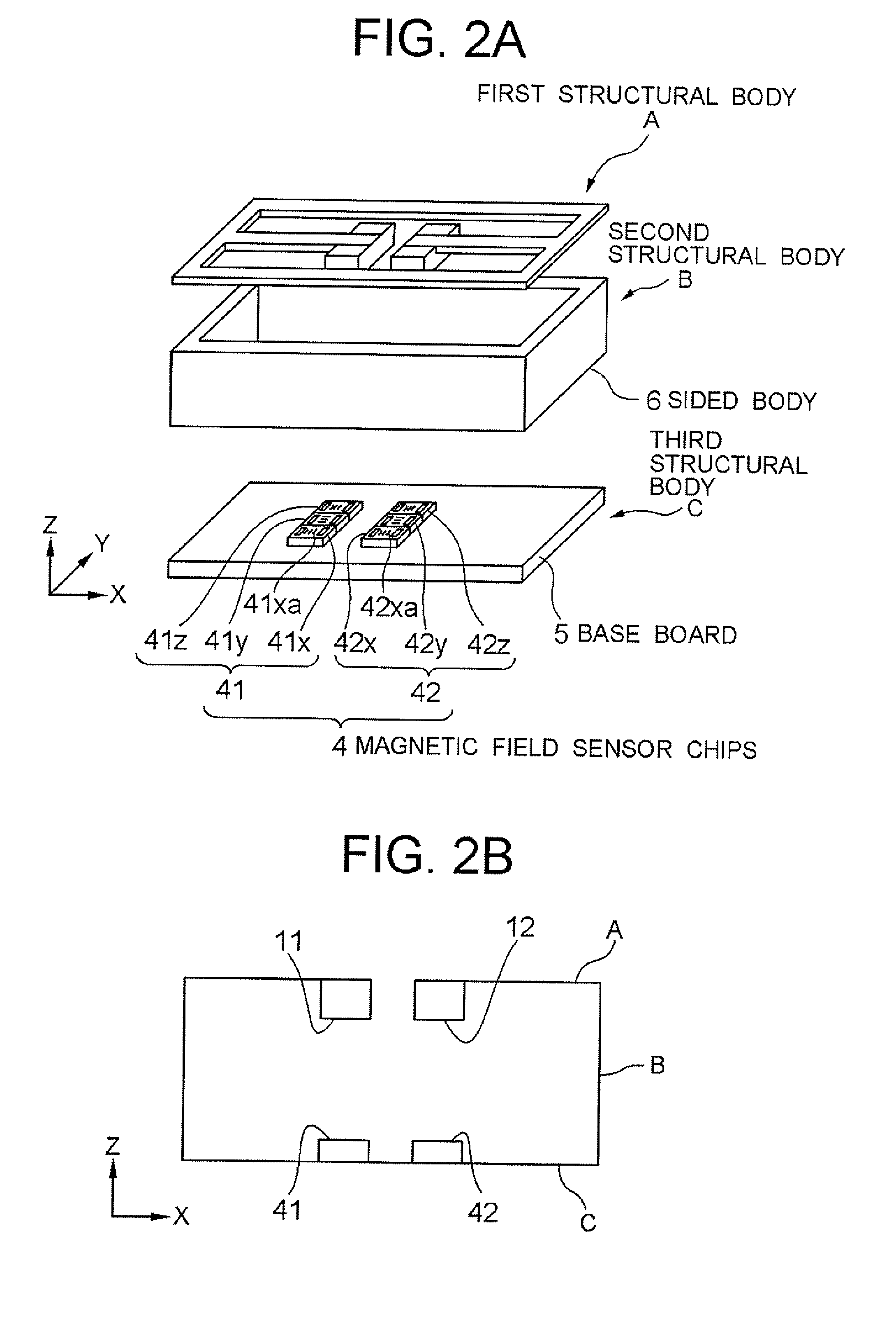
[0086] First, there will be described the structure of the acceleration sensor according to the first embodiment by referring to FIG. 1 and FIG. 2. As shown in FIG. 2A, the acceleration sensor of this embodiment is constituted roughly with three structural bodies (A, B, C). First, the first structural body A arranged at the upper part of the acceleration sensor will be described by referring to FIG. 1. FIG. 1A is a top plan view thereof and FIG. 1B is a perspective view from the bottom.

[0087] As...

second embodiment

[0120] A second embodiment of the present invention will be described by referring to FIG. 11 and FIG. 12. FIG. 11 is an illustration for showing the first structural body according to the second embodiment, including a pair of cantilevers and magnets, in which FIG. 11A is a top perspective view and FIG. 11B is a perspective view viewed from the back face side. FIG. 12 is an illustration for showing the layout of the magnetic field sensor chips in that state.

[0121] As shown in FIG. 11, a pair of cantilevers 101 according to this embodiment are arranged almost on a same straight line, and the fixed ends of each of the levers 111, 112 are arranged to oppose each other. The levers are fixed to a single plate-type supporting member 130 at each of the fixed ends. Thus, the free ends of each of the levers 111 and 112 are positioned on the opposite side from each other. With this, each of the magnets 121, 122 mounted at each free end can be arranged with a distance therebetween. Furthermo...

third embodiment

[0124] A third embodiment of the present invention will be described by referring to FIG. 13-FIG. 18. FIG. 13-FIG. 15 are illustrations for describing the measurement principle of the acceleration sensor of the third embodiment. FIG. 16-FIG. 18 are a schematic diagrams for showing a part of the structure of the acceleration sensor.

[0125] Particularly, the embodiment is distinctive in respect that: U-shaped magnets are used for the above-described magnets; the directions of the magnetic fields of the N-pole face and S-pole face are detected as the reference values; and the acceleration is obtained from the difference thereof to improve the sensitivity. In the followings, there will be described the principle for measuring the acceleration and the structure of the acceleration according to the embodiment.

[0126] First, as in the above-described first and second embodiments, the fundamental measurement principle of the acceleration sensor according to the embodiment is achieved by det...


PUM


Abstract

There is provided an acceleration sensor that is capable of detecting acceleration with high precision and capable of reducing the size and cost due to its simple structure. The acceleration sensor comprises: a pair of cantilevers arranged on a same straight line or almost in parallel in such a manner that positions of fixed ends and free ends are arranged to face in opposite directions from each other, and each of the free ends has a degree of freedom to deflect along a same direction; a pair of magnetic field generating devices mounted respectively to each of the free ends for generating magnetic fields; and a pair of magnetic field detecting devices arranged to face each of the magnetic field generating devices, respectively, for detecting directions of the magnetic fields generated by each of the magnetic field generating devices.

Description

BACKGROUND OF THE INVENTION [0001] 1. Field of the Invention [0002] The present invention relates to an acceleration sensor and, more particularly, to an acceleration sensor that measures acceleration based on a change in the direction of magnetic field. Furthermore, the present invention relates to an electronic device comprising the same and to an acceleration measuring method as well. [0003] 2. Description of the Related Art [0004] For detecting action of a prescribed object, there has been conventionally investigated the use of an acceleration sensor for detecting the acceleration of such object. For example, various applications are considered possible including operation sections of industrial robots, air-bag devices of automobiles, and hard disk drives to be loaded on portable computers, etc. Specifically, for the hard disk drive, it can be used to suppress damages to data through retracting a magnetic head by instantly detecting forcible movement and fall. Furthermore, the a...

Claims


Application Information

Patent Timeline
Patent Type & Authority Applications(United States)
IPC IPC(8): G01P15/11
CPCG01P15/18G01P15/105
Inventor KASAJIMA, TAMON
Owner SAE MAGNETICS (HK) LTD
Why Eureka
Try Eureka