Domestic combined heat and power unit

a combined heat and power unit technology, applied in steam engine plants, motors, single-network parallel feeding arrangements, etc., can solve the problems of excessive power consumption, excessive power consumption, damage to the dchp unit, etc., and achieve the effect of reducing the capacity of emergency power generation, reducing the capacity of any commercially available battery, and reducing the power outpu

Inactive Publication Date: 2008-12-02
BDR THERMEA GRP
View PDF128 Cites 14 Cited by
  • Summary
  • Abstract
  • Description
  • Claims
  • Application Information

AI Technical Summary

Benefits of technology

[0012]The primary intention is to power the dchp unit using the domestic gas supply as this is the most commonly provided source of combustible fuel. However, other combustible gases such as LPG, LNG, or biogas, or a liquid fuel may also be used. In remote dwellings having a finite liquid fuel supply which is periodically replenished, the capacity for emergency power generation is admittedly limited. However, this capacity still vastly exceeds the capability of any commercially available battery. Also, in such circumstances, the present invention is still preferable to having a separate generator as the expense of such a generator and the inconvenience of having to start the generator manually are avoided.
[0013]The current preference is to use a Stirling engine as a domestic combined heat and power unit. The Stirling engine is preferably a linear free piston Stirling engine. This offers various advantages. For example, it is a sealed unit which requires little maintenance and operates synchronously to provide a stable power output.
[0015]If the means for detecting interruption of the mains power supply is also able to detect when the main voltage or frequency of the mains power supply are outside acceptable levels a further mode of operation is possible. This allows the system to disconnect certain equipment from the mains power supply when the mains is not of a suitable quality, and supply this equipment instead from the dchp unit. In this way, sensitive equipment can be protected, while less sensitive equipment is still supplied from the mains.

Problems solved by technology

The dchp will have a maximum power output that is, typically, insufficient to provide enough power to satisfy a usual total domestic demand in the latter case.
When the system is operating without mains power, such that the only electrical power is supplied by the dchp unit, it is possible for a consumer to demand an excessive power load which may damage the dchp unit.
With this approach, the consumer is alerted to the fact that he is attempting to draw excessive power by a noticeable worsening performance of his electrical equipment (for example a dimming of the lights).
In remote dwellings having a finite liquid fuel supply which is periodically replenished, the capacity for emergency power generation is admittedly limited.
However, this capacity still vastly exceeds the capability of any commercially available battery.

Method used


Image

  • Domestic combined heat and power unit
  • Domestic combined heat and power unit
  • Domestic combined heat and power unit

Examples


Embodiment Construction

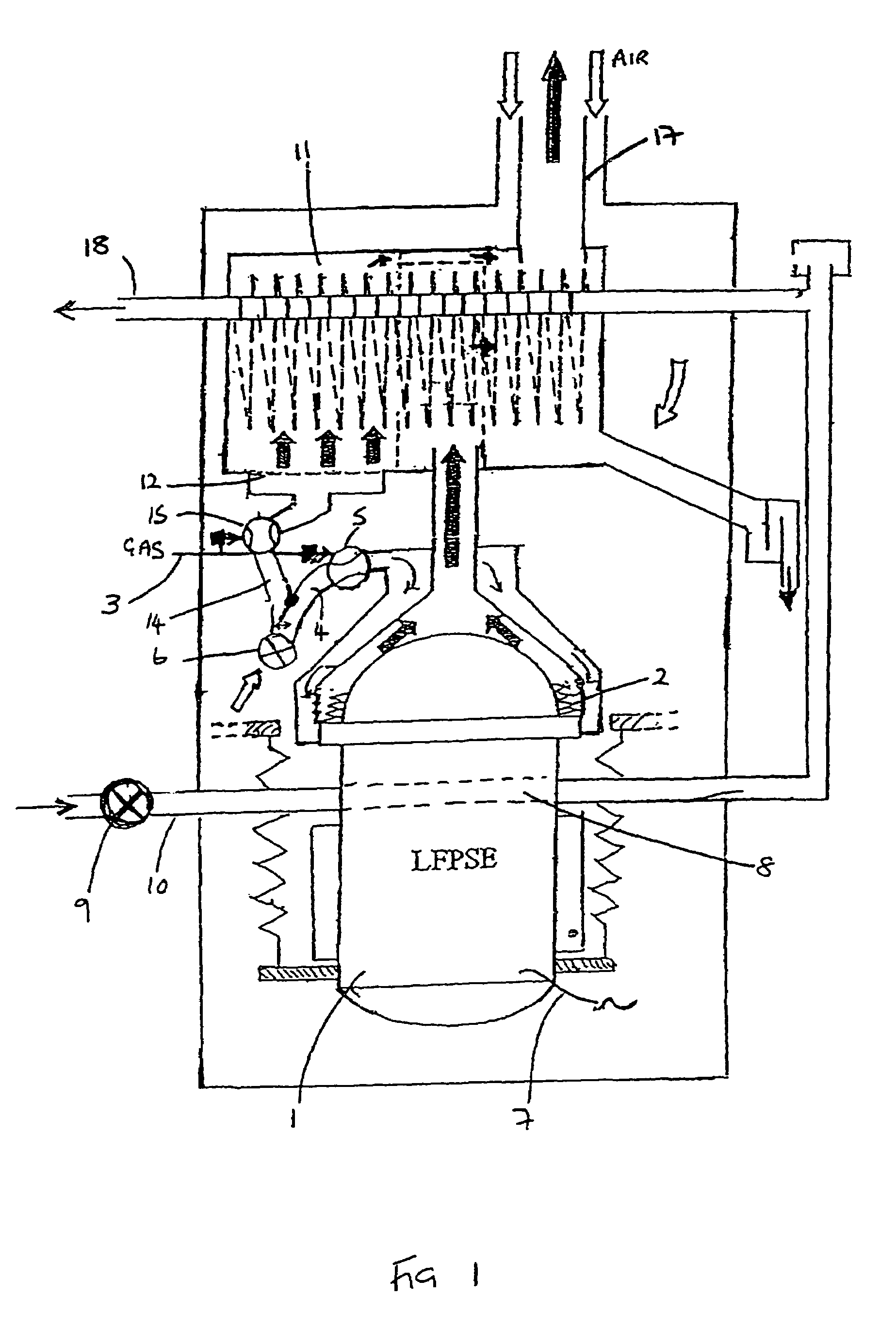
[0027]The dchp system is based around a Stirling engine 1 as shown in FIG. 1. The engine is preferably a linear free piston Stirling engine the operation of which is well known in the art. For use in a dchp system, the electrical output of the engine should be a single phase output of 16A.

[0028]The Stirling engine 1 is driven by a heat input from engine burner 2. This burner is fuelled by combustible gas supply 3 which is mixed with an air supply 4 under the control of a valve 5. The mixed stream is fed to the burner 2 by a fan 6. This drives the Stirling engine in a manner well known in the art to generate an electrical output 7 from a linear alternator. Heat is extracted from the Stirling engine at cooler 8 which is essentially a heat exchanger through which water is pumped by a pump 9 along line 10. The water passing through the cooler 8 is then further heated in a heat exchanger 11 by exhaust gas from the engine burner which has heated the head of the Stirling engine. In order t...


PUM


Abstract

A domestic combined heat and power (dchp) unit includes a Stirling engine 1 to provide heat for a domestic dwelling along with a source of electrical power. Under normal operation, the dchp is supplied with power from the national grid. When there is an interruption in the mains power from the grid, the dchp switches into a grid independent mode wherein power is generated by the dchp and is supplied to a controller 26 and to a water pump so as to maintain integrity of heat supply to the dwelling; the remaining power after that is supplied to selected domestic electrically powered equipment such as lights or television sets. The invention also discloses methods for black start of the dchp during a mains power loss, and also modification of the operating voltage on start up of electrical equipment during a power loss, to prevent the Stirling engine stalling.

Description

CROSS REFERENCE TO RELATED APPLICATIONS[0001]The present application claims priority to Great Britain Application No. 0130530.9, filed Dec. 20, 2001, which application is incorporated herein fully by this reference.[0002]The present invention relates to a domestic combined heat and power unit.BACKGROUND OF THE INVENTION[0003]The supply of electricity to domestic premises cannot always be guaranteed, and can fail due to a variety of external conditions. Domestic heating appliances generally require an electrical power supply, even where gas is the primary fuel, to power control circuitry, igniters, etc. A mains power failure therefore leaves the dwelling without its main source of heat, as well as lighting, etc. In the event of such a failure a great deal of discomfort is generally suffered by the consumer, and where the remote, very old or very young are concerned this can be a far more serious matter.[0004]Arrangements for a back-up generating facility for domestic premises general...

Claims


Application Information

Patent Timeline
Patent Type & Authority Patents(United States)
IPC IPC(8): B60L1/02F01K15/00F01K17/02F02C6/00F02C6/18F02N11/06F03D9/00H02P9/04H02J9/04F02G1/043H02J3/38H02J9/08
CPCF02G1/043H02J9/08Y02E20/14H02J9/04
Inventor ALDRIDGE, WAYNE KENNETHCLARK, DAVID ANTHONYFRANCIS, GEORGE MCCHESNEYALLDERIDGE, HEATHERROBERTS, GRAHAM RICHARD
Owner BDR THERMEA GRP
Why Eureka
Try Eureka