Power module

a power module and power technology, applied in the field of power modules, can solve the problems of increased costs, high accuracy of end plate grooves, and small gaps between end plates and cell assemblies, and achieve the effects of high reliability, easy assembly and low cos

Inactive Publication Date: 2009-01-15
PANASONIC CORP
View PDF7 Cites 26 Cited by
  • Summary
  • Abstract
  • Description
  • Claims
  • Application Information

AI Technical Summary

Benefits of technology

[0007]A power module of the invention includes: a cell stack comprising a plurality of cells that are stacked; a pair of end plates pressing and sandwiching the cell stack in the stacking direction; and a binding member joining the pair of end plates. The binding member has a recess that fits with an edge of the cell stack e...

Problems solved by technology

However, in the case of a relatively large power module including a large number of batteries, due to variations in battery size, the dimensional accuracy of the grooves of the end plates needs to be high, which results in increased costs.
Even if the dimensional accuracy of the grooves of the end plates is high, there are slight gaps betw...

Method used


Image

  • Power module
  • Power module
  • Power module

Examples


Embodiment Construction

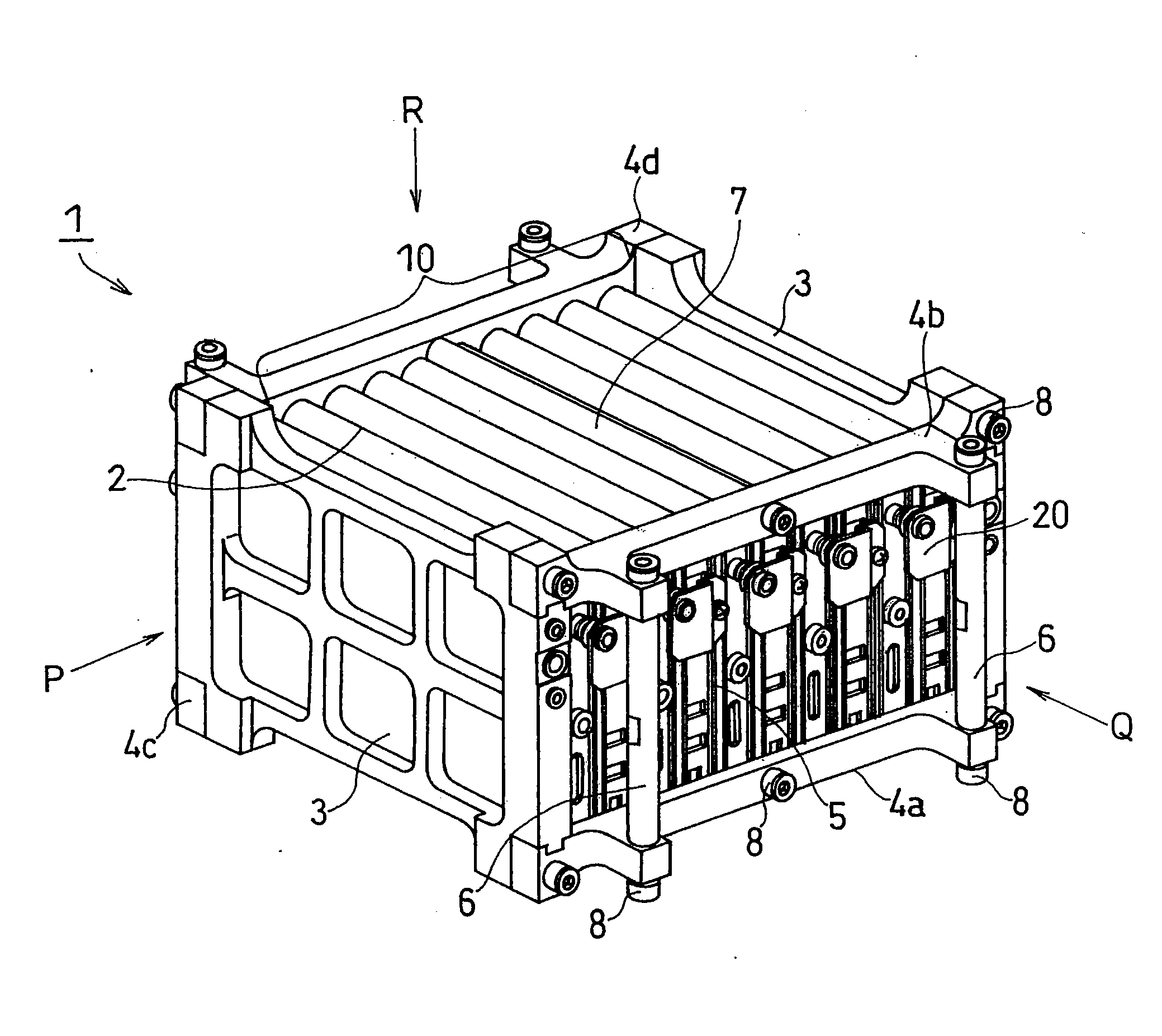
[0018]The invention relates to a power module including: a cell stack comprising a plurality of cells that are stacked; a pair of end plates pressing and sandwiching the cell stack in the stacking direction; and a binding member joining the pair of end plates. The binding member has a recess that fits with an edge of the cell stack extending in the stacking direction.

[0019]Even when the cell size is relatively large, it is possible to provide a power module in which a plurality of cells are firmly bound together in a reliable manner. It is also possible to provide an inexpensive, highly reliable power module that can be assembled easily.

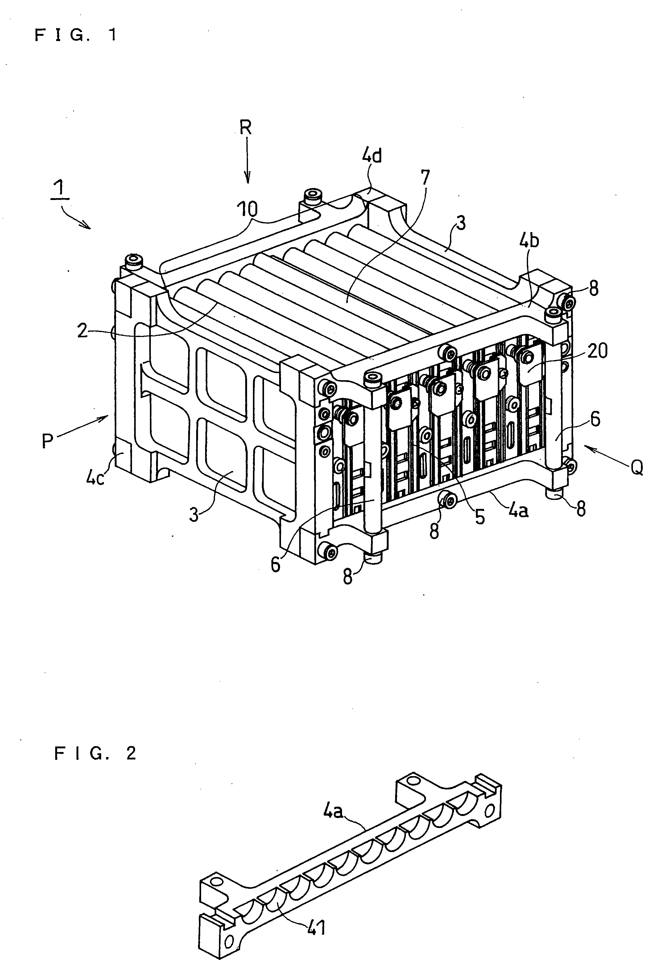
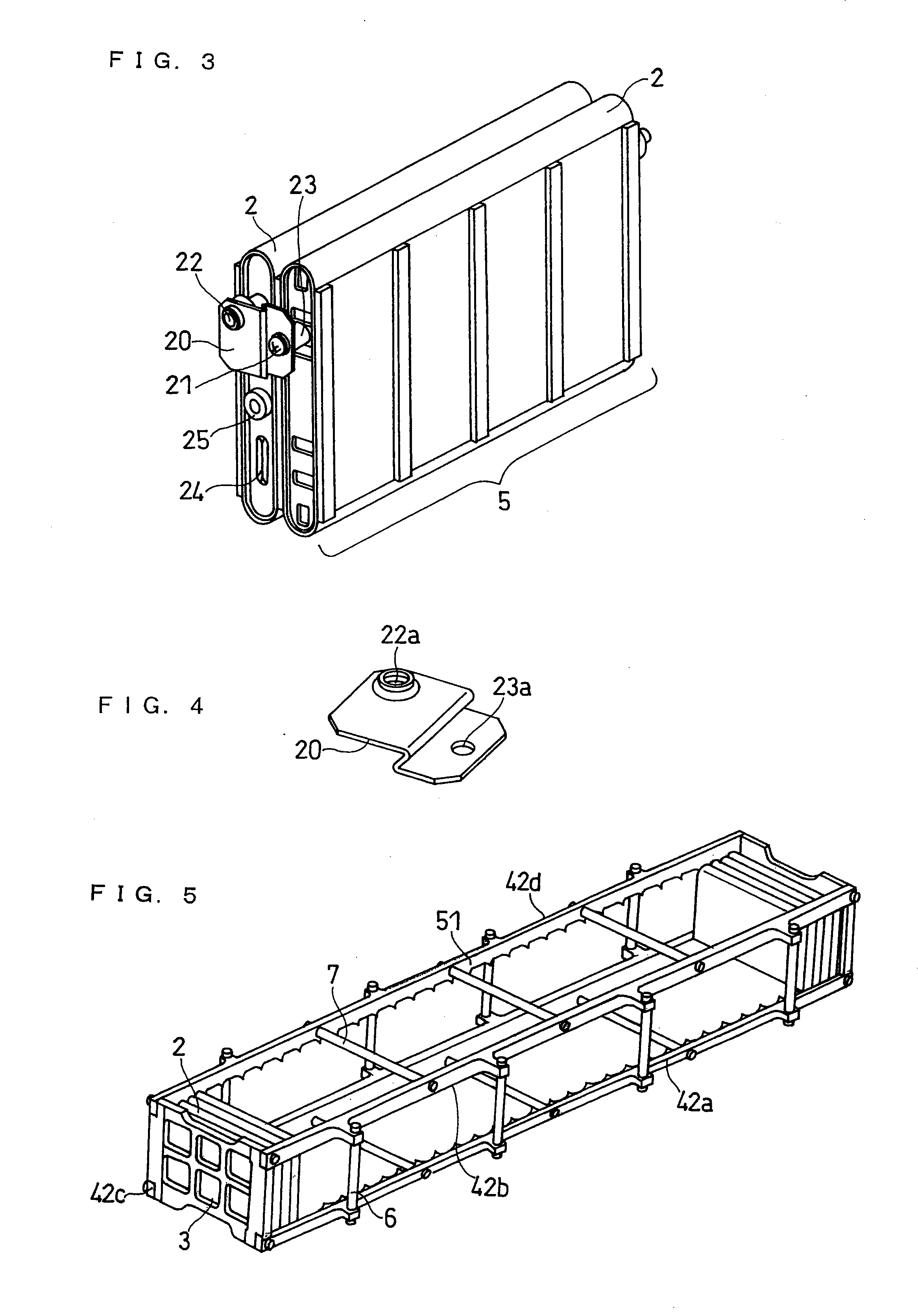
[0020]Referring now to FIGS. 1 to 4, one embodiment of the power module according to the invention is hereinafter described, but the invention is not limited to the following embodiment.

[0021]FIG. 1 is a perspective view of a power module in one embodiment of the invention. In FIG. 1, the arrow P shows a direction parallel to the stacking direction o...


PUM


Abstract

The power module of the invention includes: a cell stack including a plurality of cells that are stacked; a pair of end plates pressing and sandwiching the cell stack in the stacking direction; and a binding member joining the pair of end plates. The binding member has a recess that fits with an edge of the cell stack extending in the stacking direction. This ensures that the cells are bound together firmly and reliably.

Description

FIELD OF THE INVENTION[0001]The invention relates to a power module including a cell stack composed of a plurality of cells that are stacked, and more particularly, to a method for binding the cell stack.BACKGROUND OF THE INVENTION[0002]Conventional power modules are battery modules including one or more cell assemblies each composed of a plurality of cells that are stacked.[0003]For example, Japanese Laid-Open Patent Publication No. Hei 11-111349 proposes a power module including a battery module comprising a plurality of bar-like cell assemblies disposed in parallel, each of the cell assemblies being composed of a plurality of cylindrical cells that are connected in the axial direction in series, and a pair of synthetic resin end plates sandwiching the opposite ends of the respective cell assemblies. The pair of end plates have grooves conforming to the shape of the cells at the ends of the cell assemblies, and through-holes for exposing the electrode terminals. The opposite ends ...

Claims


Application Information

Patent Timeline
IPC IPC(8): H01M2/10H01M6/42H01M50/209
CPCH01M6/42H01M2/1061H01M50/209
Inventor MARUBAYASHI, NORIO
Owner PANASONIC CORP
Why Eureka
Try Eureka