
System and method for environmental control of an enclosure

a technology for environmental control and enclosures, applied in ventilation systems, electrical apparatus casings/cabinets/drawers, instruments, etc., can solve problems such as difficult to maintain the proper temperature of enclosures using conventional heating and cooling components, and the failure to achieve satisfactory operating conditions within enclosures

Inactive Publication Date: 2009-01-22
MOTOROLA INC
View PDF3 Cites 19 Cited by
  • Summary
  • Abstract
  • Description
  • Claims
  • Application Information

AI Technical Summary

Problems solved by technology

Maintaining satisfactory operating conditions within enclosures has been difficult to achieve in previous systems.
For instance, it is frequently difficult to maintain the proper temperature within enclosures using conventional heating and cooling components and still efficiently operate the system.
In one example of these problems, if a heater within the enclosure is activated for long periods of time, the components within the enclosure may overheat.
In another example, operating the fans more often than needed may waste substantial amounts of energy and lead to increased operating costs for the system.
However, because of the costs associated with programming the microprocessors, these microprocessor-based systems were expensive to design and build.
Additionally, when operational, these systems were often difficult to maintain.
For example, the microprocessors used in these previous systems were themselves often vulnerable to extreme environmental conditions.
However, these systems typically could not maintain a constant or nearly constant temperature within the enclosure under at least some operating conditions.
Consequently, these previous systems proved inadequate in preventing temperature swings within the enclosure and / or preventing the occurrence of over-temperature or under-temperature conditions within the enclosure.

Method used


Image

  • System and method for environmental control of an enclosure
  • System and method for environmental control of an enclosure
  • System and method for environmental control of an enclosure

Examples


Embodiment Construction

[0019]A system and method are provided that maintain satisfactory environmental conditions within enclosures without the use of microprocessors and by using only passive, non-microprocessor-based electrical or electronic components. The approaches described herein are easy to use and result in the ability to accurately and efficiently regulate and maintain environmental conditions within enclosures.

[0020]In many of these embodiments, unheated external air is selectively drawn into an electronic component housing. The external air that is drawn into the electronic component housing is selectively heated to form heated air and the extent of the heating is based at least in part upon the temperature within the electronic component housing. Either the heated air or the unheated external air is drawn across at least one electronic component positioned within the electronic component housing. A first flow of the heated air or the unheated external air that has been drawn across the electr...


PUM


Abstract

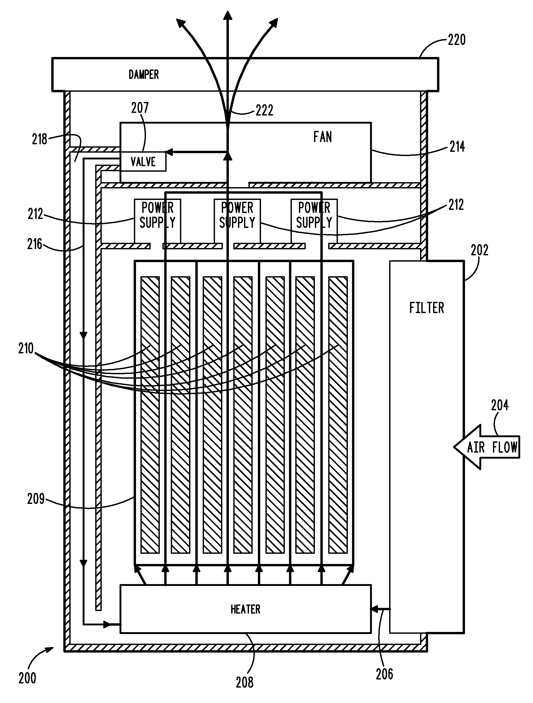
Unheated external air is drawn into an electronic component housing (200). The external air is selectively heated to form heated air (209) and the extent of the heating is based at least in part upon the temperature within the electronic component housing (200). The heated air (209) or the unheated external air (206) is drawn across at least one electronic component (210) positioned within the electronic component housing (200). A first flow (222) of either the heated air or the unheated external air is selectively exhausted from the electronic component housing (200). A first amount of the first flow (222) is based at least in part upon the temperature within the electronic component housing. A second flow (216) of either the heated air or the unheated external air is selectively re-circulated within the housing. A second amount of the second flow (216) is based at least in part upon the temperature within the housing (200). The influx, heating, exhausting, and re-circulating operate so as to cause the temperature within the housing (200) to stay within a predetermined range.

Description

RELATED APPLICATIONS[0001]This application is related to a co-pending application entitled “APPARATUS AND METHOD FOR AIR CIRCULATION,” filed on even date herewith, assigned to the assignee of the present application, and hereby incorporated by reference.FIELD OF THE INVENTION[0002]The field of the invention relates generally to environmental enclosures and more particularly to managing the environmental conditions within enclosuresBACKGROUND OF THE INVENTION[0003]Enclosures are used to retain different types of electronic components and protect these components from extreme environmental conditions or hazards. For example, in cellular communication systems, base station components are typically housed in enclosures to protect the components from extreme heat or cold. In this case, the components may include circuit boards that perform the various functions of the base stations. Other components may also be used within the enclosures. For example, heaters may be used to heat the elec...

Claims


Application Information

Patent Timeline
IPC IPC(8): F24F7/013G05D23/30H05K5/00
CPCG05D23/025G05D23/1906H05K7/207H05K7/20618H05K7/20172F24F7/08H04B1/036
Inventor GUTIERREZ, GREG M.FRENDREISS, DAVID M.GIBSON, CHRISTOPHER J.LARSEN, KEVIN J.NESTOR, MARC N.TUROCY, JAMES W.WARYCH, DAN B.BERRIMAN, ROBERT A.
Owner MOTOROLA INC
Learn More