Suspension Structure for a Work Machine

a work machine and suspension technology, applied in the direction of suspensions, vehicle components, transportation items, etc., to achieve the effect of improving durability and reducing the operating frequency of the operation changing uni

Active Publication Date: 2009-01-22
KUBOTA LTD
View PDF9 Cites 8 Cited by
  • Summary
  • Abstract
  • Description
  • Claims
  • Application Information

AI Technical Summary

Benefits of technology

[0026]Accordingly, in cases where an operation changing unit is provided for the suspension mechanism in the work vehicle suspension structure, the operating frequency of the operation changing unit can be reduced, a construction that is advantageous from the standpoint of the durability of the operation changing unit can be obtained, and the durability of the operation changing unit can be improved.

Problems solved by technology

Accordingly, this is greatly disadvantageous from the standpoint of the durability of the operation changing unit.

Method used


Image

  • Suspension Structure for a Work Machine
  • Suspension Structure for a Work Machine
  • Suspension Structure for a Work Machine

Examples


first modified embodiment

of the Invention

[0073]A construction such as that shown in FIG. 7 may also be used instead of the construction shown in FIG. 6 of the previous “Preferred Embodiments of the Invention”.

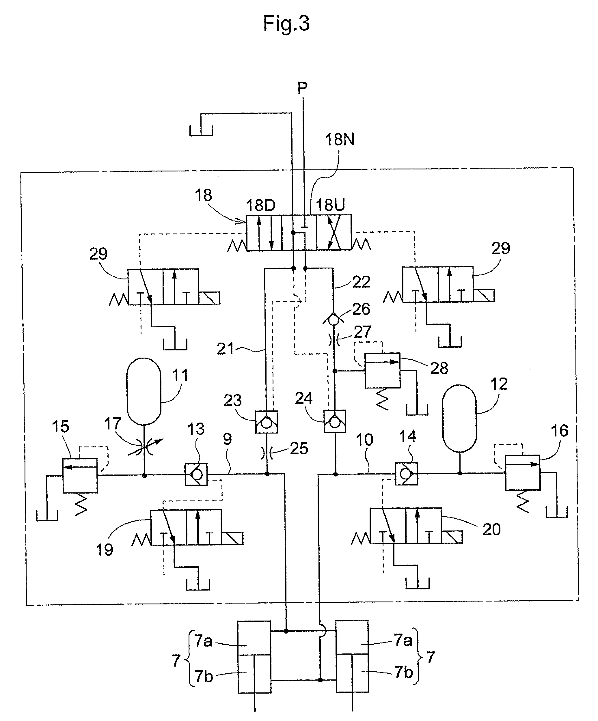
[0074]As is shown in FIG. 7, a number of times of calculation N is set in the control device, and the number of times of calculation N is first set at “0” (step S10). The control valve 18 is set in the neutral position 18N, steps S12 through S16 similar to steps S2 through S6 in FIG. 6 are performed in a state in which the check valves 13 and 14 are placed in an open state (a state in which the hydraulic cylinders 7 are operated as a suspension mechanism (step S11), and the intermediate position B1 is detected.

[0075]When the intermediate position B1 is detected, the intermediate position B1 and the target range H1 are compared (step S17), and if the intermediate position B1 departs from the target range H1 on the body lowering side, “1” is subtracted from the calculated number of times N (step S18); if...

second modified embodiment

of the Invention

[0082]In cases where the set time T11 is set as a slightly longer time in steps S2 through S6 in FIG. 6 in the “Preferred Embodiments of the Present Invention” and steps S12 through S16 in FIG. 7 of the “First Modified Embodiment of the Present Invention”, and a construction is used which detects a plurality of maximum positions A1 and a plurality of minimum positions A2, the neutral position B1 in step 6 of FIG. 6 and step S16 of FIG. 7 may be detected as followed.

[0083](1) In a plurality of maximum positions A1 and a plurality of minimum positions A2, a single maximum position A1 and a single minimum position A2 are taken as one set. These are divided into a plurality of sets of maximum and minimum positions A1 and A2; a plurality of intermediate positions B1 are detected by detecting an intermediate position B1 in each set, and the average value of the plurality of intermediate positions B1 is taken as the intermediate position B1 in step S6 of FIG. 6 and step S16...

third modified embodiment

of the Present Invention

[0085]Rather than set the intermediate position B1 at the center position of the maximum and minimum positions A1 and A2 in the “Preferred Embodiments of the Present Invention”, “First Modified Embodiment of the Present Invention”, and “Second Modified Embodiment of the Present Invention”, the intermediate position B1 may be set at a position slightly on the body raising side (extension side of the hydraulic cylinders 7) from the center position between the maximum and minimum positions A1 and A2 on the basis of the presence or absence and type of the working apparatus mounted on the front part of the body (e.g., front loader), working configuration or the like, or is set at a position slightly on the body lowering side (retraction side of the hydraulic cylinders 7) from the center position between these maximum and minimum positions A1 and A2.

[0086]For example, in cases where a working apparatus (e.g., front loader) is mounted on the front part of the body, ...


PUM


Abstract

An arrangement is provided in which the durability of an operation changing means is improved when this means is provided to the suspension mechanism in a suspension structure for a work vehicle. A maximum position (A1) and minimum position (A2) of the operation of the suspension mechanism are detected, and an intermediate position (B1) between the maximum and minimum positions (A1) and (A2) is detected. When the intermediate position (B1) departs from the target range (H1), the operation of the suspension mechanism is changed to the body raising side or body lowering side so that the intermediate position (B1) moves toward the target range (H1).

Description

BACKGROUND OF THE INVENTION[0001]1. Field of the Invention[0002]The present invention relates to a suspension structure for a work machine such as a farm tractor or the like.[0003]2. Description of the Related Art[0004]Farm tractors, which constitute one example of a work machine, include tractors that have a front-wheel suspension mechanism, as disclosed, for example, in U.S. Pat. No. 6,145,859. Suspension mechanisms are generally mechanisms which absorb indentations and protrusions in the ground surface by operating on the raising side and lowering side in accordance with such indentations and protrusions in the ground surface, and thus improve the riding comfort.[0005]Because of numerous indentations and protrusions in the operating area over which the work vehicle runs compared to paved roadways, and because a working apparatus is usually mounted on a work vehicle, the operating position of the suspension mechanism may be displaced from the target range on the body raising side ...

Claims


Application Information

Patent Timeline
Patent Type & Authority Applications(United States)
IPC IPC(8): B60G17/04
CPCB60G17/056B60G2500/302B60G2400/252B60G2300/082B60G9/02
Inventor IWAMI, KENICHIHAYASHI, SHIGEKIUEDA, YOSHIHIRO
Owner KUBOTA LTD
Why Eureka
Try Eureka