High Speed Flatbed Scanner Comprising Digital Image-Capture Module with Two-Dimensional Optical Image Photo-Sensor or Digital Camera
- Summary
- Abstract
- Description
- Claims
- Application Information
AI Technical Summary
Benefits of technology
Problems solved by technology
Method used
Image
Examples
example 1
Using Digital Image Capture Module
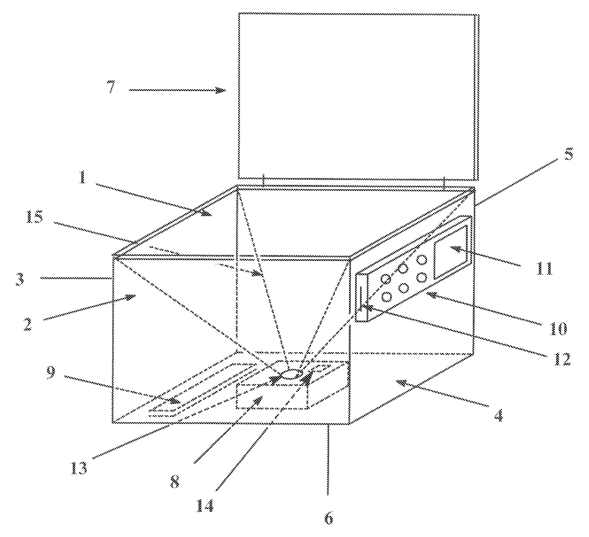
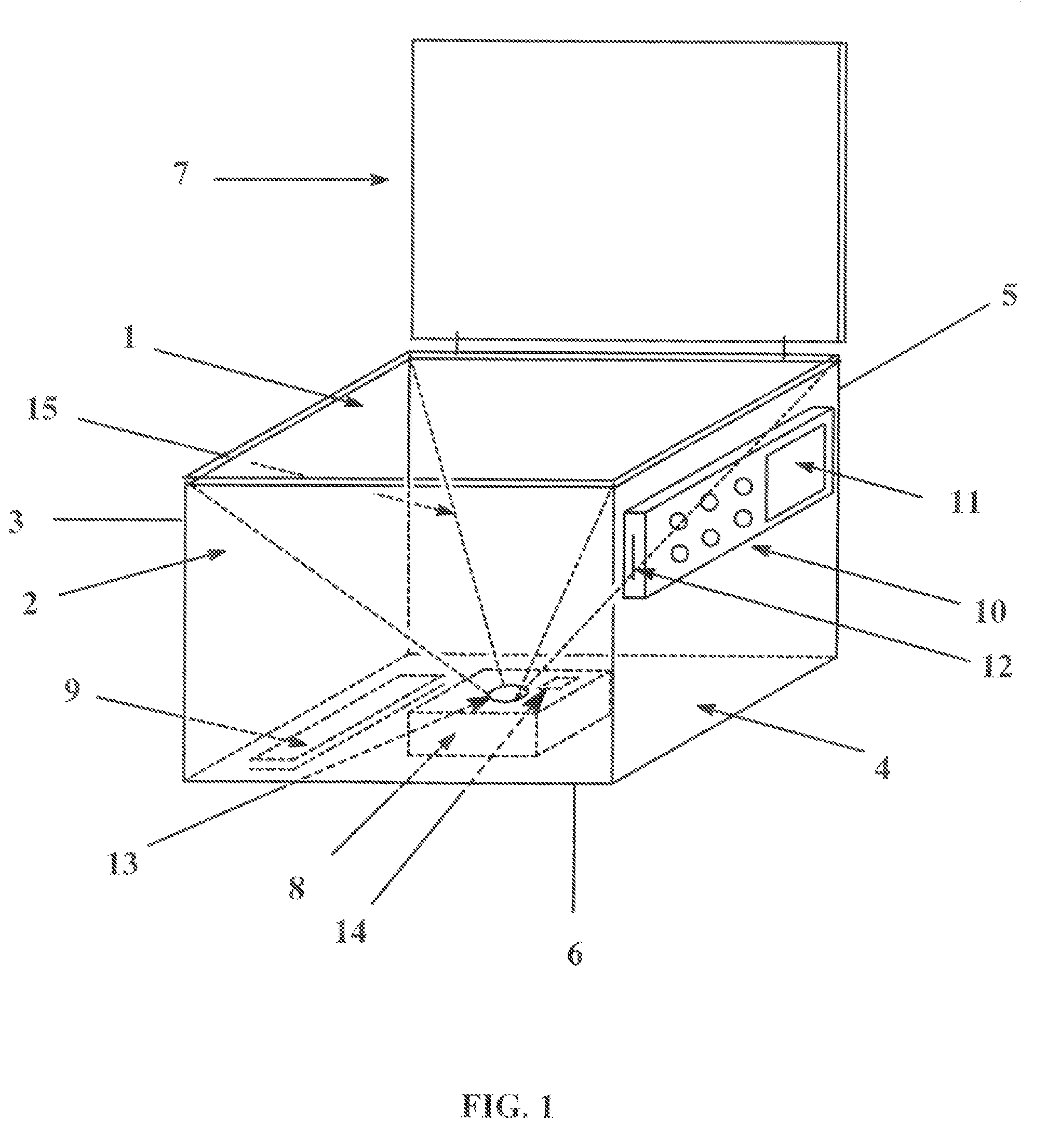
[0112]One embodiment of the present invention will be described in detail be referring to the accompanying drawings and in particular to FIG. 5, a flatbed scanner constructed in accordance with the present invention comprises a top platen 1, front platen 2, two side platens 3 and 4, a rear platen 5, and a bottom platen 6, all of which constitute a housing or an enclosure. At least the top platen 1 which is the scanning window is a transparent or light-transmitting platform on which a document to be scanned (not shown) is positioned. The top platen 1 is positioned at the top and supported on the housing. The scanning window area is extended to the edge of the thin frame supporting the scanning windows to provide enough scanning glass room making it easier to scan or capture the images of hard to scan bound documents having small margins such as thick books for example especially near the binding edge without any distortion at the protruding binding e...
example 2
Using Digital Camera or Digital Video Camera
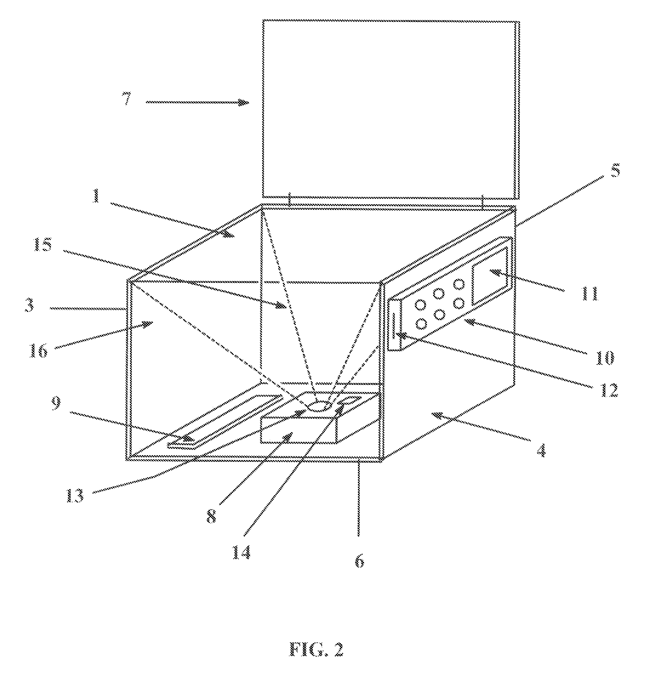
[0121]A second embodiment of the present invention will be described in detail by referring to the accompanying drawings and in particular to FIG. 1, a flatbed scanner constructed in accordance with the present invention comprises a top platen 1, front platen 2, two side platens 3 and 4, a rear platen 5, and a bottom platen 6, all of which constitute a housing or an enclosure. At least the top platen 1 which is the scanning window is a transparent or light-transmitting platform on which a document (not shown) to be scanned is positioned. The top platen 1 is positioned at the top and supported on the housing. The scanning window area is extended to the edge of the thin frame supporting the scanning windows to provide enough scanning glass room making it easier to scan or capture the images of hard to scan bound documents having small margins such as thick books for example especially near the binding edge without any distortion at the protr...
example 3
Flatbed Scanner for Bound Documents
[0129]In a third embodiment of the present invention described herein with reference to the drawings and in particular to FIGS. 2 through 6, a flatbed scanner suitable for copying bound documents is constructed in accordance with the present invention as shown in Examples 1 and 2 wherein at least both the top platen 1 and the front platen 16 are transparent or light transmissive and both form an L-shaped angle there between. The top platen 1 and front platen 16 make up the L-shaped scanning window and are positioned to support the opposing faces of a bound document during use. The edge, where both the top platen 1 and front platen 16 meet, is small enough so as to provide enough scanning glass room making it easy to scan bound documents such as thick books for example especially near the binding edge without any distortion at the protruding binding edge or causing damage to the binding. The binding edge of the book is placed at the corner of a top ...
PUM
 Abstract
Description
Claims
Application Information
 - R&D
- Intellectual Property
- Life Sciences
- Materials
- Tech Scout
- Unparalleled Data Quality
- Higher Quality Content
- 60% Fewer Hallucinations
Browse by: Latest US Patents, China's latest patents, Technical Efficacy Thesaurus, Application Domain, Technology Topic, Popular Technical Reports.
© 2025 PatSnap. All rights reserved.Legal|Privacy policy|Modern Slavery Act Transparency Statement|Sitemap|About US| Contact US: help@patsnap.com


