Stacked heat-transfer interface structure

a heat-transfer interface and stacking technology, applied in the field of cooling modules, can solve the problems of affecting heat dissipation efficiency, and generating a lot of heat during working, so as to avoid stress damage, save material preparation, and be smooth attached to the surface

Active Publication Date: 2009-01-22
ADLINK TECH INC
View PDF12 Cites 19 Cited by
  • Summary
  • Abstract
  • Description
  • Claims
  • Application Information

AI Technical Summary

Benefits of technology

[0011]According to another aspect of the present invention, the second heat-transfer sheet members of the first heat transfer devices are elastically deformable so that the second heat-transfer sheet members are differently deformed to compensate for the height tolerance of the first heat generating electronic devices of the circuit board when the heat plate and the circuit board are fastened together, avoiding stress damage to the first heat generating electronic devices of the circuit board.
[0012]According to still another aspect of the present invention, the heat plate has a plurality of mounting holes, the circuit board has a plurality of mounting holes respectively fastened to the mounting holes of the heat plate by fastening members, and elastic members are respectively sleeved onto the fastening members and stopped between the heat plate and the circuit board to absorb shocks and to buffer the pressure between the heat plate and the circuit board, and therefore the heat plate can be smoothly attached to the surface of an external metal shell when assembled with the circuit board.
[0013]According to still another aspect of the present invention, a full range of sizes of the second heat transfer devices are provided for selection so that different stacked heat heat-transfer interface structures can easily be assembled to fit different circuit boards having different heights of first and second heat generating electronic devices. By means of modularized fabrication, the invention saves material preparation and facilitates the assembly of the desired stacked heat heat-transfer interface structure.

Problems solved by technology

These electronic devices require much power and generate much heat during working.
Further, the mounting stability between the heat sink and the circuit board also affects heat dissipation efficiency.
Because the heat generating electronic devices of a circuit board for industrial computer show elevational differences, it is complicated to select and install heat sinks in a circuit board for industrial computer and to keep the installed heat sinks in positive contact with the respective heat generating electronic devices of the circuit board.
This installation procedure is complicated and costs a lot.
Further, after bonding of a heat sink to a circuit board, the flat contact surface of the heat sink may be not positively kept in close contact with all heat generating electronic devices or contact spots, resulting in low dissipation efficiency and production of a thermal resistance.
However, a heat-transfer plate of this design has a low thermal conductivity, resulting in low dissipation efficiency.
In general, when a conventional heat sink is installed in a circuit board to dissipate heat from heat generating electronic devices of the circuit board, the heat sink may be not closely attached to all the contact surfaces of the heat generating electronic devices, and any gap produced in between the heat transfer surface of the heat sink and the heat generating electronic devices affects spreading of heat energy from the heat generating electronic devices through the heat sink, lowering the heat dissipation efficiency.

Method used


Image

  • Stacked heat-transfer interface structure
  • Stacked heat-transfer interface structure
  • Stacked heat-transfer interface structure

Examples


Embodiment Construction

[0018]For easy understanding of the features of the present invention, we briefly explain the materials used for regular heat transfer devices and their physical properties. The heat transfer effect of a heat transfer device, such as heat sink or heat plate, is determined subject to the heat conductivity of the heat sink or heat plate. The higher the heat conductivity is, the higher the heat transfer effect will be. On the contrary, if the heat transfer device has a low heat conductivity, the heat transfer effect of the heat transfer device will be poor. However, a heat transfer of relatively higher heat conductivity has a relatively lower thermal resistance and lower wall thickness, therefore a heat transfer device having a relatively higher heat conductivity is less elastic when compared to a heat transfer device having a relatively lower heat conductivity.

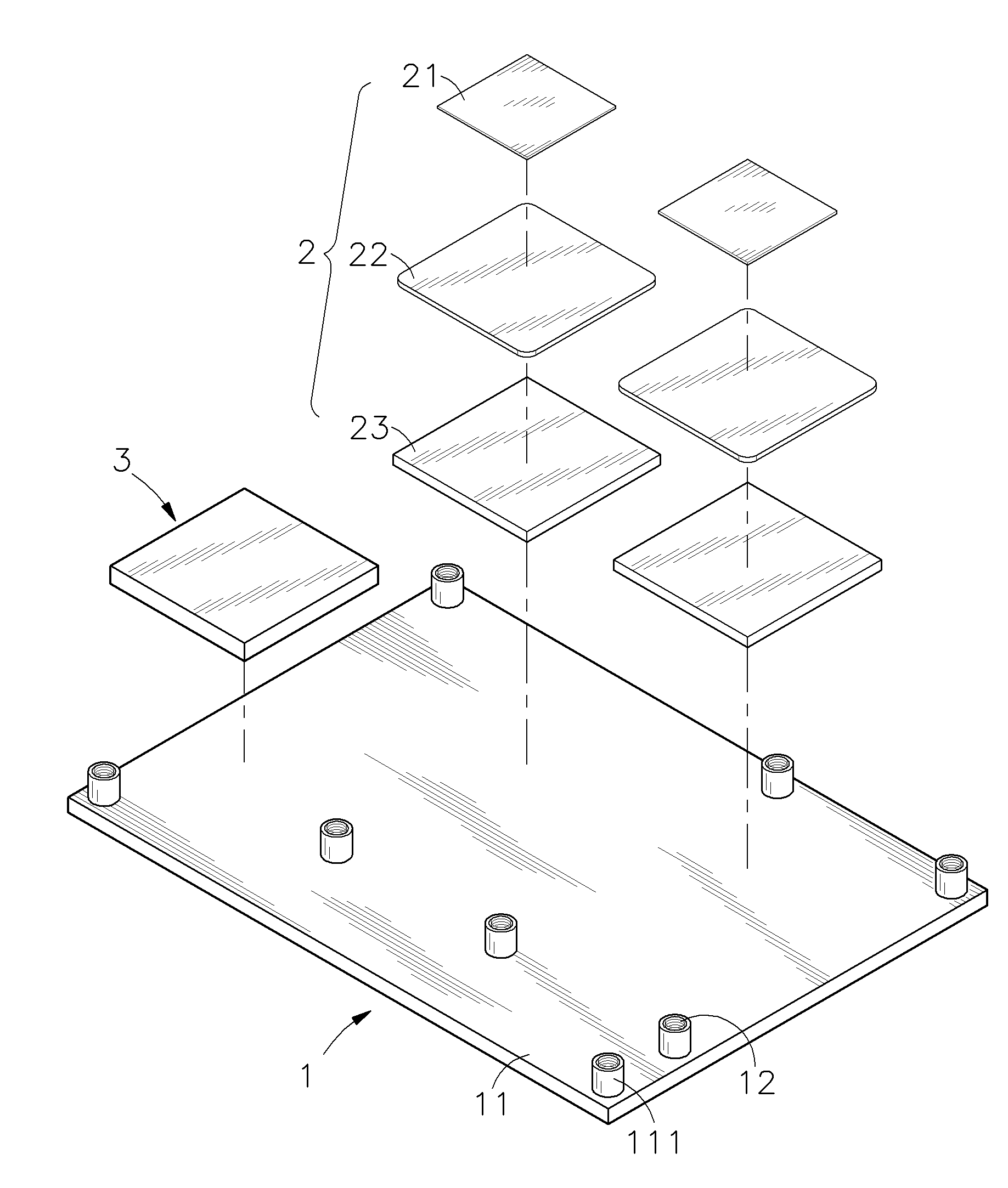
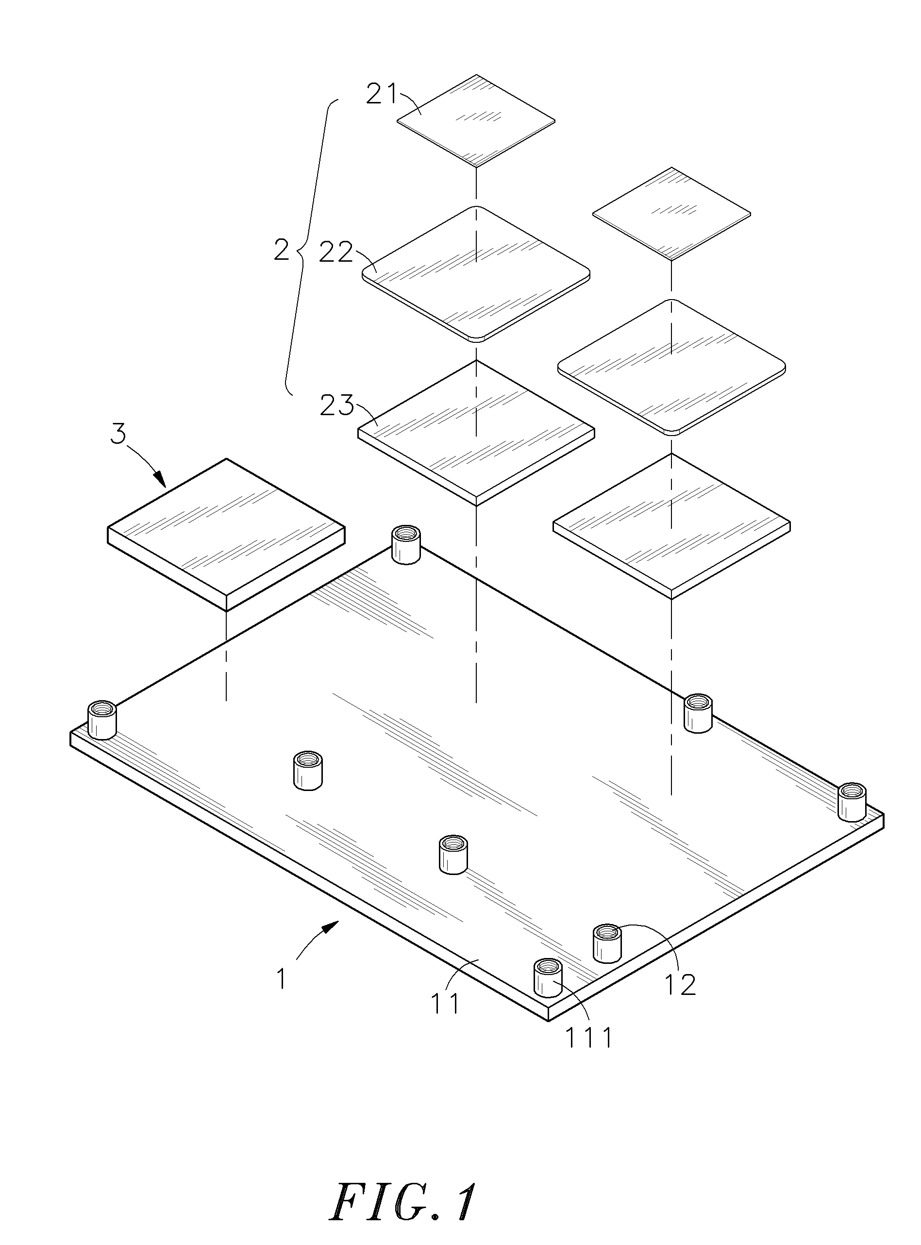
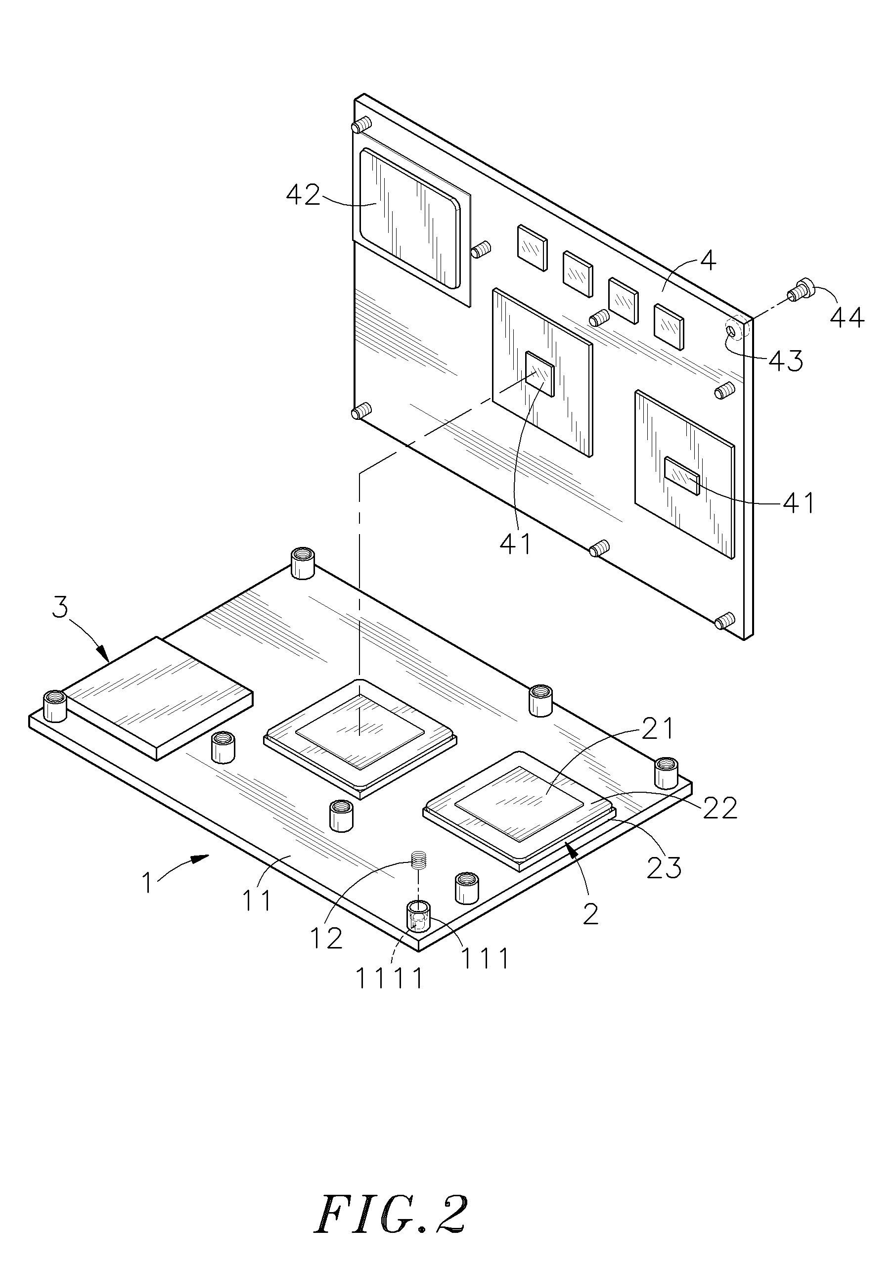
[0019]Referring to FIGS. 1 and 2, a stacked heat-transfer interface structure in accordance with the present invention is show...


PUM


Abstract

A stacked heat-transfer interface structure for dissipating heat from a circuit board is disclosed to include a heat plate affixed to the circuit board, and relatively thinner first heat transfer devices and relatively thicker second heat transfer devices respectively attached to first and second heat generating electronic devices of the circuit board that have different heights for transferring heat from the first and second heat generating electronic devices of the circuit board to the heat plate for dissipation. Each first heat transfer device comprises a first heat-transfer sheet member having a high heat conductivity and a low thermal resistance and bonded to one first heat generating electronic device, an elastically deformable second heat-transfer sheet member having a low heat conductivity and a high thermal resistance and bonded to the heat plate to compensate for height tolerance of the respective first heat generating electronic device, and a heat-transfer block for spreading heat energy from the first heat-transfer sheet member onto the heat plate through the second heat-transfer sheet member.

Description

[0001]This application is a Continuation-In-Part of my patent application Ser. No. 11 / 469,478, filed on Aug. 31, 2006.BACKGROUND OF THE INVENTION[0002]1. Field of the Invention[0003]The present invention relates to cooler modules and more particularly, to a stacked heat-transfer interface structure, which has first and second heat transfer devices thereof respectively attached to first and second heat generating electronic devices of a circuit board to compensate for height differences and to effectively and evenly transfer heat energy from the first and second heat generating electronic devices to a heat plate for quick dissipation.[0004]2. Description of the Related Art[0005]Advanced electronic devices commonly have a high-density design and light, thin, short and small characteristics. These electronic devices require much power and generate much heat during working. In order to effectively dissipate heat energy from multiple heat generating electronic devices, high-performance h...

Claims


Application Information

Patent Timeline
Patent Type & Authority Applications(United States)
IPC IPC(8): H05K7/20
CPCH01L23/3672H01L23/4006H01L23/433H01L2023/405H01L2023/4056H01L2924/0002H01L2023/4081H01L2924/00
Inventor FANG, CHIH-LIANG
Owner ADLINK TECH INC
Why Eureka
Try Eureka