Lever-type connector

a technology of lever-type connectors and lever-type parts, which is applied in the direction of coupling device connection, coupling/disconnecting parts engagement/disengagement, electrical apparatus, etc., can solve the problems of difficult finger-pointing by operators on the release portion, inability of the lock to obtain the necessary flexure, etc., to achieve shorten the entire length of the lever-locking part, and sufficient flexure of the elastic pi

Active Publication Date: 2009-01-22
SUMITOMO WIRING SYST LTD
View PDF5 Cites 23 Cited by
  • Summary
  • Abstract
  • Description
  • Claims
  • Application Information

AI Technical Summary

Benefits of technology

[0009]The release portion of the lever-locking part is interposed between the fixed end and the lock. Thus, it is possible to shorten the entire length of the lever-locking part, as compared with the case where the fixed end, the lock and the release portion are arranged in a row. The distance between the fixed end and the lock is long. Therefore, a sufficient flexure amount of the elastic piece can be achieved when the lock is locked to the receiving portion.
[0010]The lever preferably has an arm and an operation part at the end of the arm. The cam groove is formed in the arm and the operation part is configured to be held by the operator's fingers for operating the lever. The lever-locking part preferably is on the operation part. The fixed end preferably is at one end of the operation part in a rotational direction thereof, and the lock preferably is at other end of the operation part in the rotational direction thereof. As a result, it is possible to obtain sufficient flexure of the elastic piece and a favorable feeling in the locking operation without making the lever large.

Problems solved by technology

However, it then is impossible for the lock to obtain a necessary flexure for locking the lock to the lever-locking part-receiving portion.
Further it is difficult for an operator to put fingers on the release portion.

Method used


Image

  • Lever-type connector
  • Lever-type connector
  • Lever-type connector

Examples


Embodiment Construction

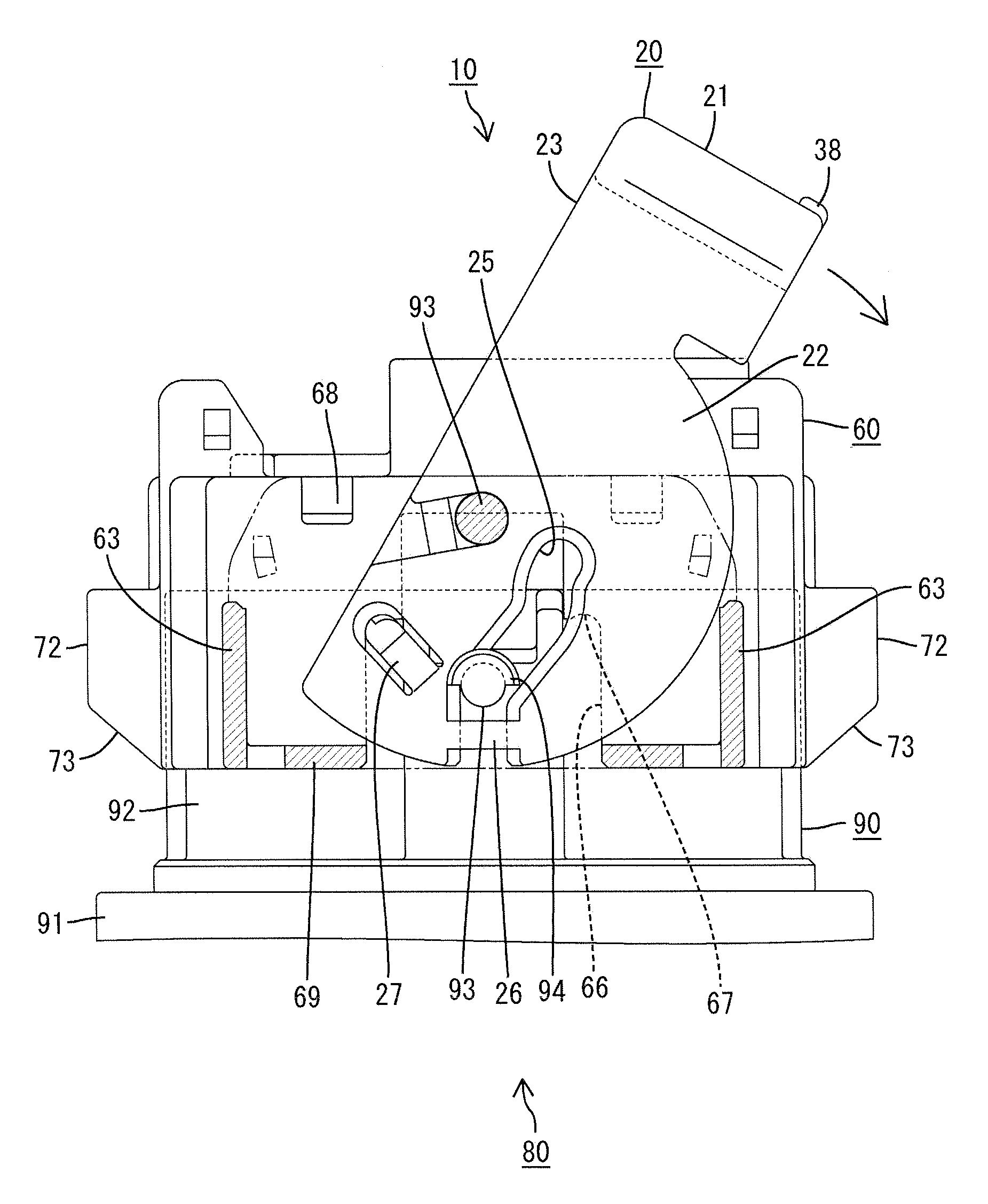
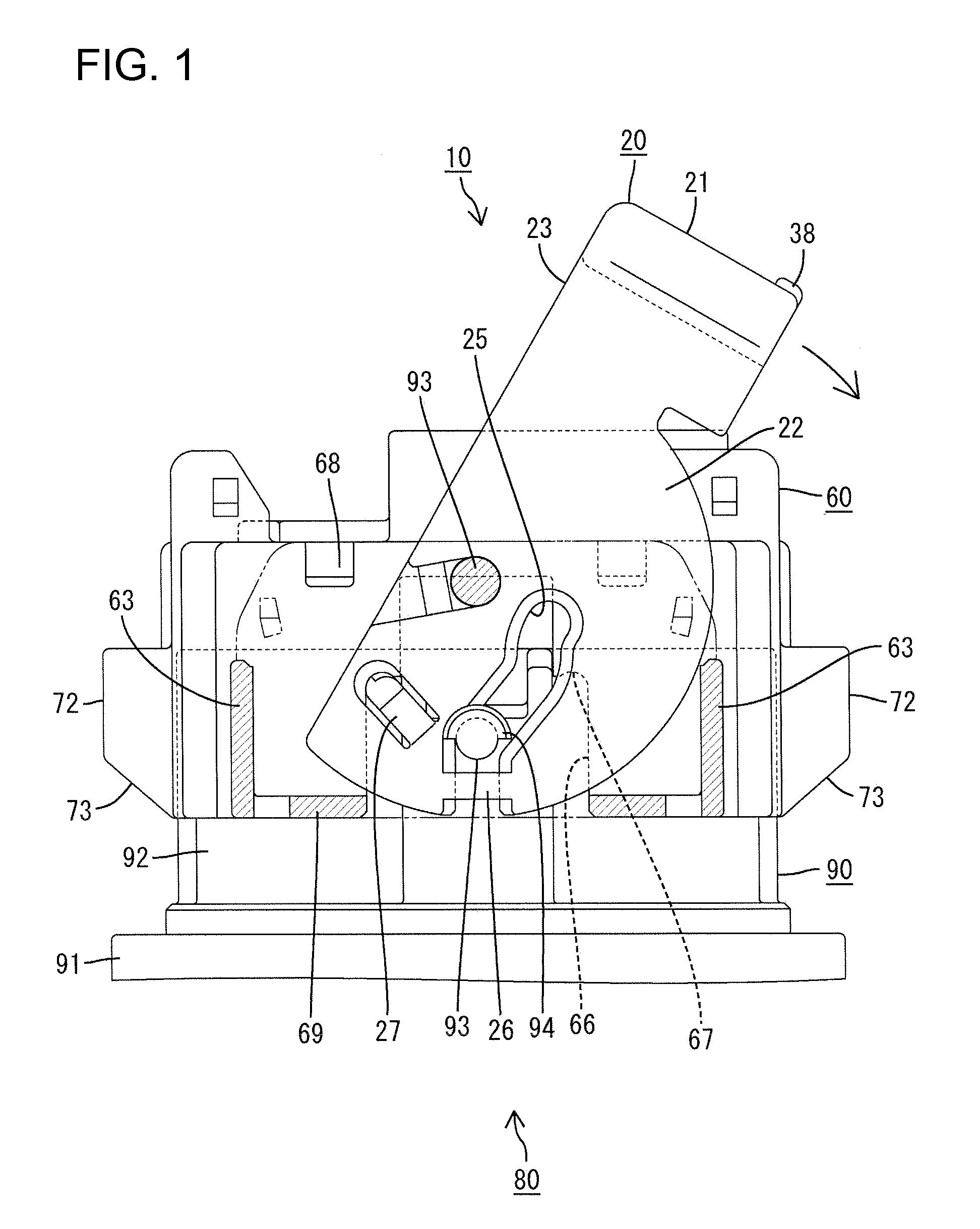
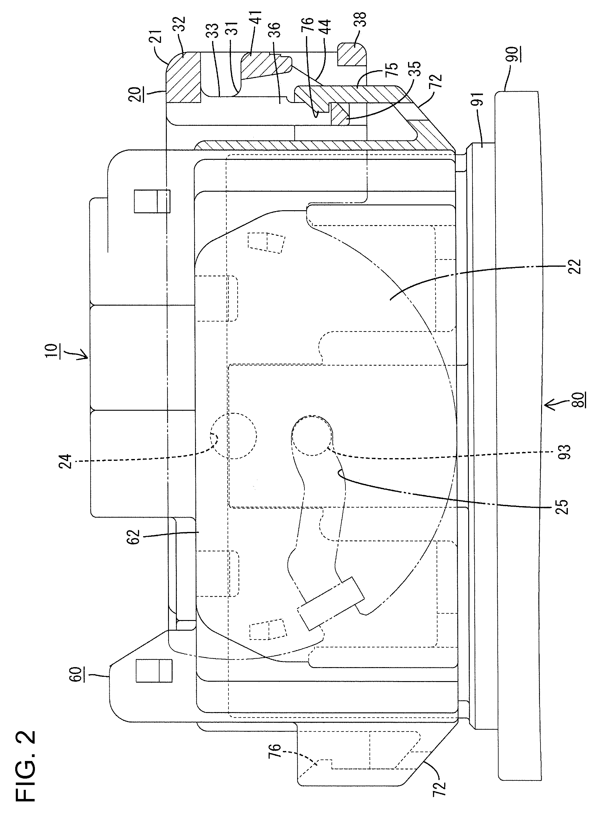
[0021]A lever-type connector in accordance with the invention is identified by the numeral 10 in FIGS. 1 through 4. The connector 10 has a lever 20, a housing 60, and terminal fittings (not shown). The lever 20 can be rotated to fit the housing 60 in a mating connector 80 or to separate the housing 60 therefrom. In the following description, the end at which the housing 60 is fit in the mating connector 80 is referred to as the front.

[0022]The mating connector 80 is constructed as a male connector and has a mating housing 90 made of synthetic resin. The mating housing 90 has a terminal accommodation part 91, as shown in FIG. 9. A wide rectangular hood 92 projects forward from the terminal accommodation part 91 and is open at the front end. Male terminal fittings (not shown) of different sizes are mounted in the terminal accommodation part 91 and front ends of the terminal fittings project into the hood 92.

[0023]Upper and lower cam pins 93 project at a widthwise center of both upper ...


PUM


Abstract

A lever-type connector (10) has a housing (60) for engaging a mating connector (80). A lever (20) is supported rotatably by the housing (60) and is configured for assisting connection of the connectors (10, 80). The lever (20) has a lever-locking part (31) with a deformable elastic piece (33). A lock (35) on the elastic piece (33) engages a receiving portion (72) on the housing (60) for holding the lever (20) in a rotation-prevented state. A release portion (41) formed separately from the lever-locking part (31) can be pressed to displace the elastic piece (33) in a direction for separating the lock (35) from the receiving portion (72).

Description

BACKGROUND OF THE INVENTION[0001]1. Field of the Invention[0002]The invention relates to a lever-type connector.[0003]2. Description of the Related Art[0004]U.S. Pat. No. 7,172,442 discloses a lever-type connector that has a housing configured for fitting to a mating connector and a lever supported rotatably on the housing. The lever has an operation part and arms that project from opposite ends of the operation part. Thus the lever is U-shaped and is mounted to straddle the housing. Each arm has a cam groove for engaging a cam pin on the mating connector. The lever is rotated while the cam pin engages the cam groove to produce a cam action for moving the connector and the mating connector towards one another.[0005]The arm of the lever has a lever-locking part for holding the lever in a rotation-prevented state when the lever has finished a rotation. The lever-locking part has an elastic piece with a fixed end and a free end that is elastically deformable around the fixed end. A loc...

Claims


Application Information

Patent Timeline
Patent Type & Authority Applications(United States)
IPC IPC(8): H01R13/62
CPCH01R13/62955H01R13/62938
Inventor MIZOGUCHI, ATSUSHIHORIUCHI, MASAYA
Owner SUMITOMO WIRING SYST LTD
Why Eureka
Try Eureka