Centrifugal machine

a centrifugal machine and centrifugal technology, applied in the direction of centrifuges, etc., can solve the problems of self-excited vibration problem, temperature dependence of damping characteristic (damping constant) of the vibration preventive rubber, vibration of the rotor, etc., and achieve the effect of increasing the damping amount of the vibration generated

Inactive Publication Date: 2009-01-22
KOKI HLDG CO LTD
View PDF10 Cites 16 Cited by
  • Summary
  • Abstract
  • Description
  • Claims
  • Application Information

AI Technical Summary

Benefits of technology

[0007]One of objects of the present invention is to provide a centrifugal machine including a vibration preventive mechanism which can increase the damping amount of the vibration generated in the vibratory system thereof.
[0008]Another of objects of the present invention is to provide a centrifugal machine including a vibration preventive mechanism which can restrict the temperature dependence of the vibration damping amount of the vibration preventive rubber.
[0009]According to an aspect of the present invention there is provided a centrifugal machine comprising a box member; a drive device mounted within the box member and having a rotation shaft; a rotor connected to the rotation shaft of the drive device for holding a specimen to be centrifuged; and, a damper for mounting the drive device into the box member, wherein the centrifugal machine further includes a vibration preventive mechanism part, the vibration preventive mechanism part containing a support member to be supported by the box member and a damping portion disposed in the support member so as to be connectable or contactable to the drive device, and also wherein, on receiving a vibration change from the drive device, the vibration preventive mechanism part can dampen the vibration change using the damping portion.

Problems solved by technology

Also, the vibration of the rotor, which is generated due to the imbalance of the rotor itself and due to the imbalance of the capacity, mass and the like of a specimen to be loaded into the rotor, is also transmitted to the drive device not only through the rotor but also through the rotation shaft, and is dampened by vibration preventive rubber (a damper) which supports the drive device.
The vibration involved with the centrifugal machine raises the following two major problems.
The first is a self-excited vibration problem.
Also, the second problem is that, as disclosed in the below-mentioned patent reference 3, the damping characteristic (damping constant) of the vibration preventive rubber has temperature dependence.
However, to increase the number of provision of the vibration preventive rubber does not increase the damping amount (damping constant) but increases the spring reaction force that is given by the vibration preventive rubber.
As a result of this, the box member becomes easy to vibrate, which makes it difficult to secure a sufficient damping amount.

Method used


Image

  • Centrifugal machine
  • Centrifugal machine
  • Centrifugal machine

Examples


Embodiment Construction

[0018]Now, description will be given below in detail of an embodiment of a centrifugal machine according to the invention with reference to the accompanying drawings. In all figures, parts having the same function are given the same designations and the repeated description thereof will be omitted.

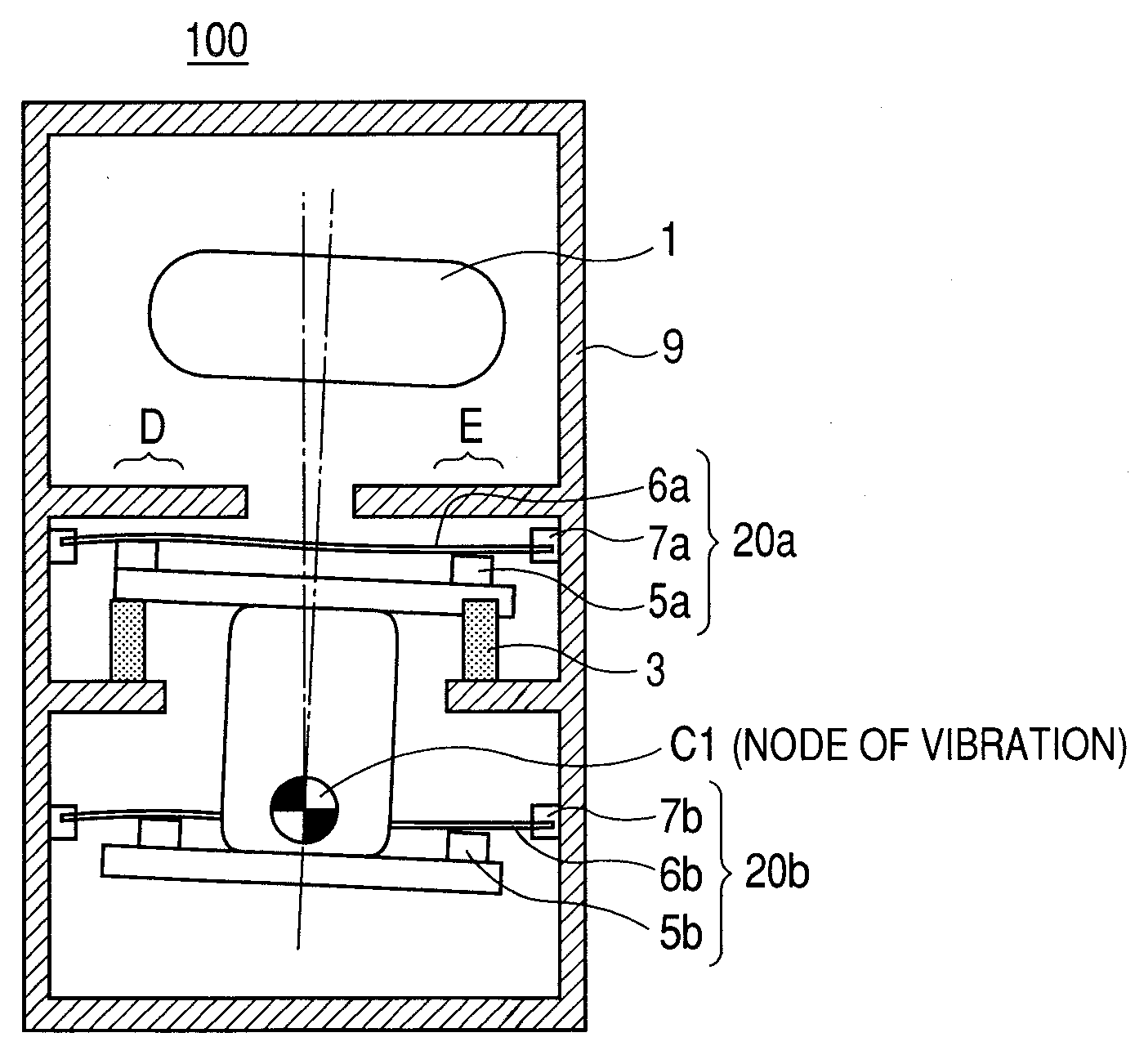
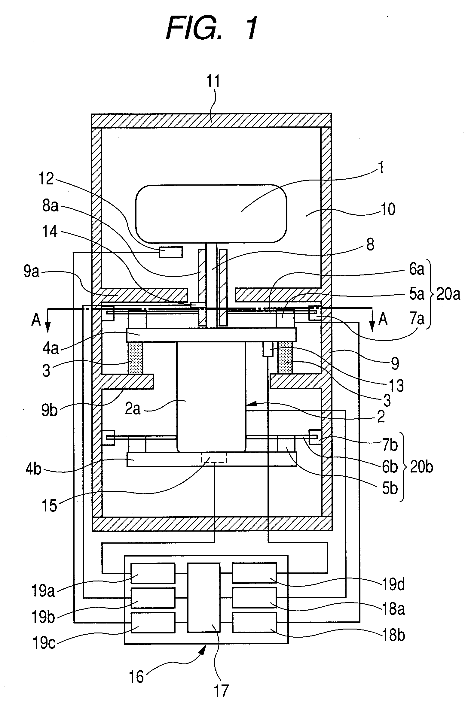
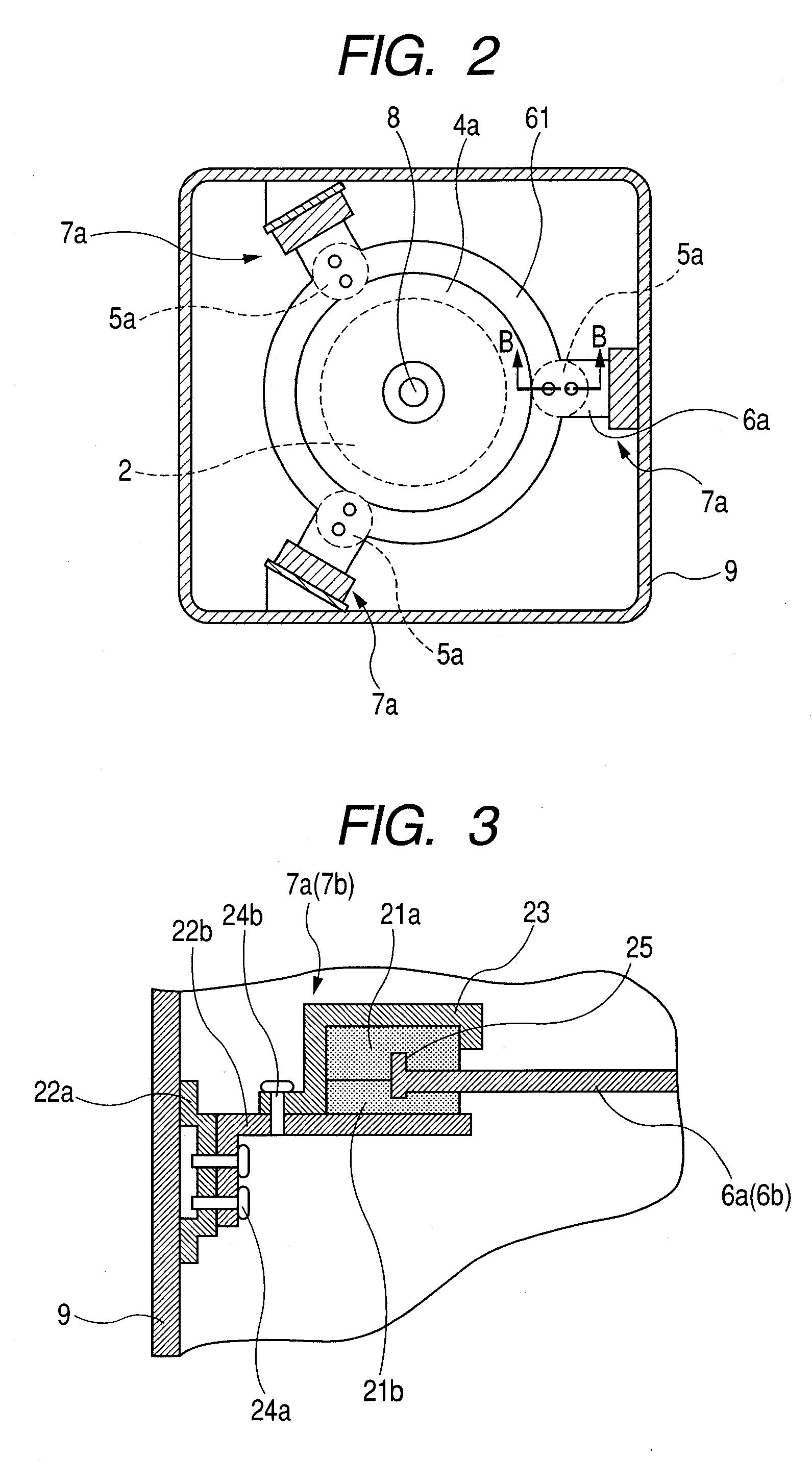
[0019]FIG. 1 is a structure view of a centrifugal machine according to an embodiment of the invention. FIG. 2 is a section view of the centrifugal machine, taken along the A-A line shown in FIG. 1. FIG. 3 is a structure view of a support portion of a vibration preventive mechanism employed in the centrifugal machine shown in FIG. 1. FIG. 4 is a section view of a friction damping portion included in the vibration preventive mechanism of the centrifugal machine shown in FIG. 1. FIGS. 5 and 6 are respectively section views of the centrifugal machine shown in FIG. 1, showing the vibration modes thereof. FIG. 7 is a structure view of another embodiment of the friction damping portion of the vib...


PUM


Abstract

A centrifugal machine comprises a box member; a drive device mounted within the box member and having a rotation shaft; a rotor connected to the rotation shaft of the drive device for holding a specimen to be centrifuged; and, a damper for mounting the drive device into the box member, wherein the centrifugal machine further includes a vibration preventive mechanism part, the vibration preventive mechanism part containing a support member to be supported by the box member and a damping portion disposed in the support member so as to be connectable or contactable to the drive device, and also wherein, on receiving a vibration change from the drive device, the vibration preventive mechanism part can dampen the vibration change using the damping portion.

Description

CROSS-REFERENCE TO RELATED APPLICATIONS[0001]This application is based upon and claims the benefit of priority from Japanese Patent Application No. 2006-237480, filed Sep. 1, 2006, the entire contents of which are incorporated herein by reference.BACKGROUND OF THE INVENTION[0002]A centrifugal machine is an apparatus in which a specimen to be centrifuged is inserted into a rotor through a tube or a bottle, the rotor is coupled to the rotation shaft of a drive device made of a motor, and the rotor is rotated at a high speed to thereby centrifuge and refine the specimen. The rotation speed of the centrifugal machine varies depending on the use of the specimen to be centrifuged and refined; and, according to the uses of the centrifugal machines, generally, there are supplied various types of centrifugal machines the rotation speeds of which range from a low rotation speed of several thousands of rpm to a high rotation speed of 150,000 rpm or so. The types of rotors to be driven by the d...

Claims


Application Information

Patent Timeline
Patent Type & Authority Applications(United States)
IPC IPC(8): B04B9/14B04B13/00
CPCB04B9/14B04B9/12
Inventor KUSUMOTO, SHOJIOHTSU, SHINKI
Owner KOKI HLDG CO LTD
Why Eureka
Try Eureka