Insertion assisting device and endoscope apparatus

a technology of which is applied in the field of insertion assisting device and endoscope apparatus, can solve the problems of air pressure interference, difficult to move the insertion assisting device smoothly, and difficult to insert the insertion portion into the deep digestive tract, so as to enhance the operationality of reduce the number of long tubes exposed to the outside, and smooth withdraw the insertion assisting device

Inactive Publication Date: 2009-01-22
FUJI PHOTO OPTICAL CO LTD
View PDF19 Cites 19 Cited by
  • Summary
  • Abstract
  • Description
  • Claims
  • Application Information

AI Technical Summary

Benefits of technology

[0037]With the configuration of [13], since the balloon is mounted on the outer circumference of the distal-end portion of the insertion assisting device, the distal-end portion of the insertion assisting device can be fixed to the inside of the body by inflating the balloon. Further, when the insertion assisting device is withdrawn while the balloon inflates, the air accumulated in the body can be discharged to the outside from the ventilation hole through the ventilation duct. Therefore, it is possible to smoothly withdraw the insertion assisting device.
[0038]According to the above-described insertion assisting device, since the liquid storage unit is provided, the liquid such as the body fluid flowing into the ventilation duct through the ventilation hole is stored in the liquid storage unit. Therefore, the liquid can be prevented from leaking and contaminating a working region.
[0039]Also, according to the above-described endoscope apparatus, since the ventilation duct of the insertion assisting device is connected to the suction device through the duct, which is provided in the endoscope apparatus, the number of long tubes exposed to the outside can be decreased as compared with the case where the ventilation duct of the insertion assisting device is directly connected to the suction device. Therefore, it is possible to enhance the operationality of the insertion assisting device.

Problems solved by technology

Therefore, if an insertion portion of an endoscope is merely pushed, the pushing force is hardly transmitted to the distal end of the insertion portion, which makes it difficult to insert the insertion portion into the deep digestive tract.
In the endoscope apparatus of JP 2002-301019 A, however, if the insertion assisting device is moved in a withdrawal direction in a state where the balloon of the insertion assisting device is inflated and is in close contact with the intestine wall, it is difficult to move the insertion assisting device smoothly.
This is because the air being accumulated in the base-end side of the balloon of the insertion assisting device is compressed such that the air pressure interferes with the withdrawal operation of the insertion assisting device.
Then, the liquid may leak from the end portion of the air insertion path and may contaminate a working region.

Method used


Image

  • Insertion assisting device and endoscope apparatus
  • Insertion assisting device and endoscope apparatus
  • Insertion assisting device and endoscope apparatus

Examples


first embodiment

[0092] the on / off operation of suction is switched by closing the opening 97 of the grasp portion 62. However, instead of the opening 97, an opening and closing valve may be provided in the duct 74 such that the duct 74 is opened to the atmosphere or is blocked from the atmosphere by opening or closing valve.

[0093]Next, a second embodiment of the invention will be described. FIG. 7 is a diagram schematically showing the duct configuration of the second embodiment. The second embodiment shown in FIG. 7 is different from the first embodiment shown in FIG. 3 in that the opening 97 of the grasp portion 62 and the suction pump 120 in the first embodiment are not provided, and that a check valve 130 is provided in the pipe 124.

[0094]The check valve 130 is a member for preventing gas from flowing into the pipe 124 from the outside (that is, a gas flow from the base end to the distal end within the duct 74). FIGS. 8SA and 8B show the configuration of the check valve 130. The check valve 130...

second embodiment

[0095]In the second embodiment configured in such a manner, when the pressure in the vicinity of the openings 90 increases, the air surrounding the openings 90 is naturally discharged to the outside through the openings 90, the duct 74, the tube 98, the pipe 122, the liquid reservoir tank 116, and the pipe 124. At this time, since liquid such as body fluid flowing from the openings 90 is stored in the liquid reservoir tank 116, it is possible to prevent the liquid from leaking and contaminating a working region.

[0096]Also, in the second embodiment, the check valve 130 is provided. Therefore, even when the pressure in the vicinity of the openings 90 decreases, the liquid within the duct 74 can be prevented from flowing backward into the body from the openings 90.

[0097]In the second embodiment, the position of the check valve 130 is not limited to the pipe 124, but may be provided in any position of the flow path communicating with the duct 74. Furthermore, without the pipe 124 being ...

third embodiment

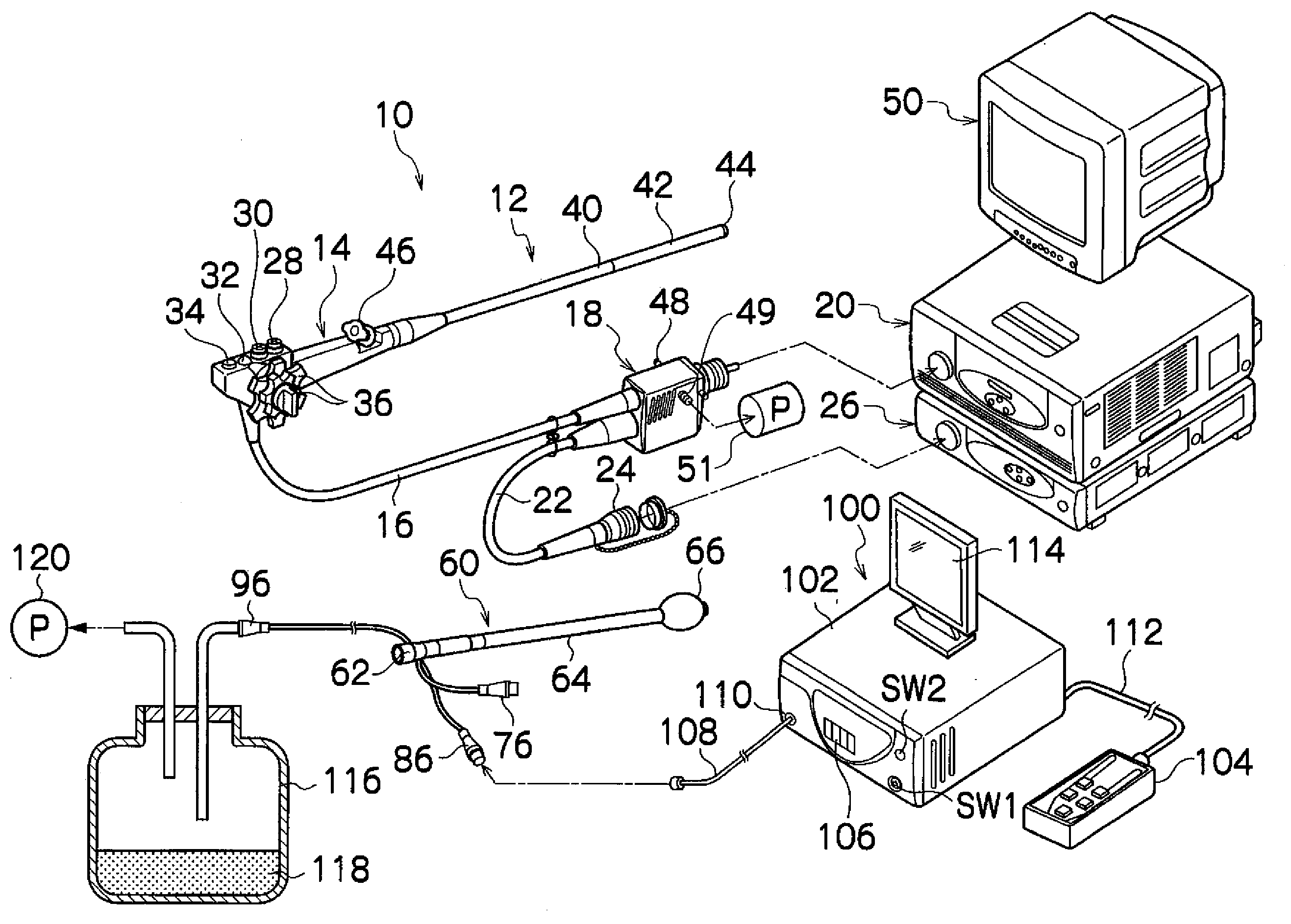
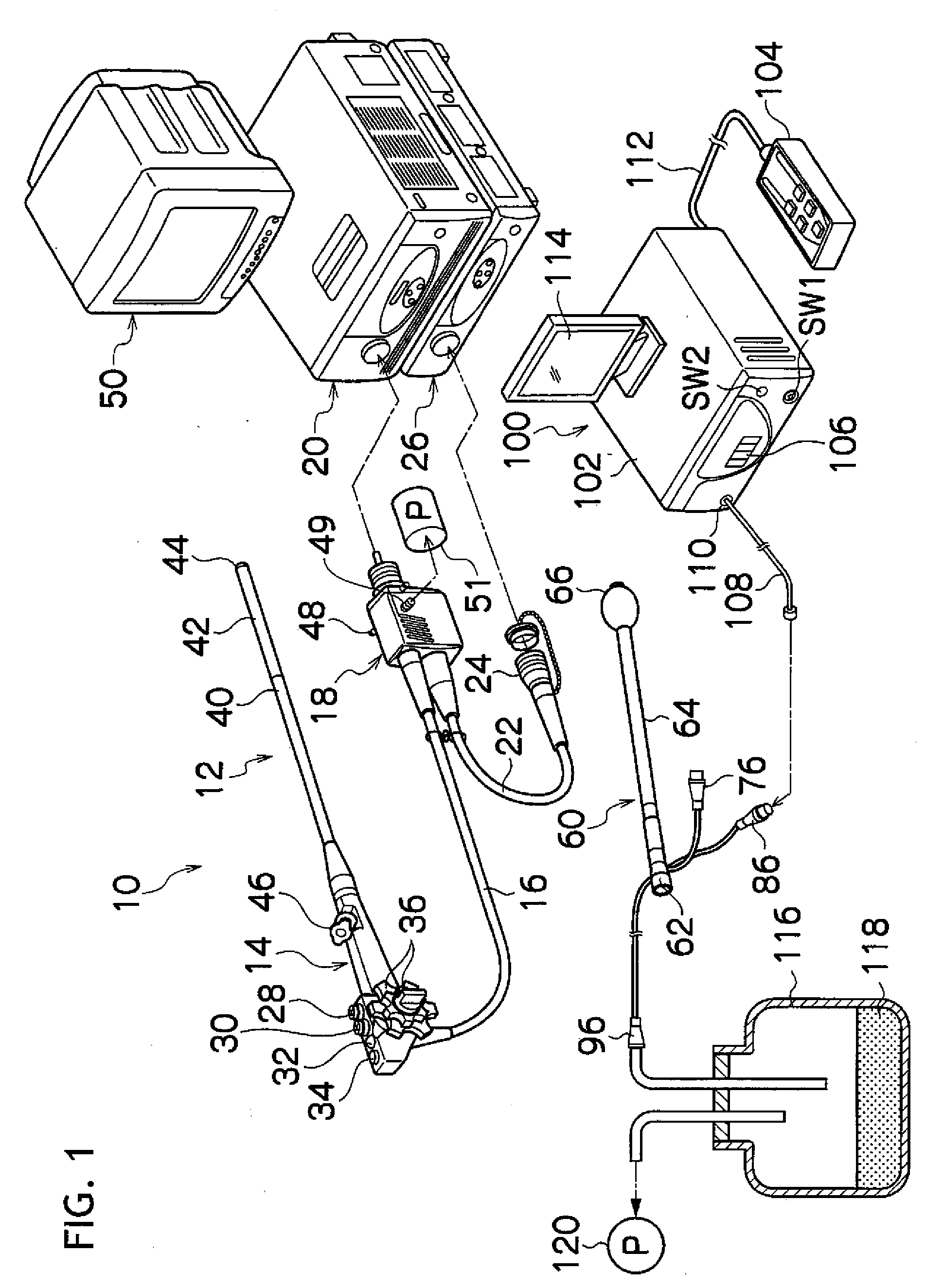
[0103]FIG. 11 is a diagram showing the system configuration of the endoscope apparatus according to the invention. As shown in FIG. 11, the endoscope apparatus mainly includes an endoscope 10′, an insertion assisting device 60′, and a balloon control device 100.

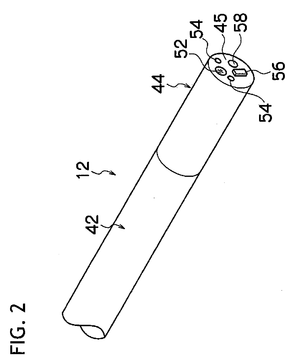
[0104]As shown in FIG. 2, the observation optical system 52, the pair of illumination optical systems 54 and 54, the air / water supply nozzle 56, and the forceps port 58 are provided on the distal-end surface 45 of the distal-end portion 44.

[0105]As shown in FIG. 12, the air / water supply nozzle 56 is connected to an air / water supply tube 51′. The air / water supply tube 51′ diverges into an air supply tube 53 and a water supply tube 55′ such that the air supply tube 53′ and the water supply tube 55′ are connected to a valve 57′ disposed in the hand operation unit 14. The valve 57′ is connected to an air feed tube 59′ and a water feed tube 61′ and has an air / water supply button 28′ attached thereto. In a state where the air / water...


PUM


Abstract

An insertion assisting device 60 has an insertion path 70 into which an insertion portion 12 of an endoscope 100 is inserted and has a substantially tubular shape. The insertion assisting device 60 includes a ventilation opening 90 that is formed on a distal-end surface or outer circumferential surface thereof, a ventilation duct 74 that communicates with the opening 90 and is different from the insertion path 70, and a liquid reservoir tank 116 that is connected to a base-end side of the duct 74 and stores liquid flowing out of the duct 74.

Description

CROSS-REFERENCE TO RELATED APPLICATIONS[0001]This application is based upon and claims the benefit of priority from the Japanese Patent Application Nos. 2007-187156 and 2007-187157 both fled on Jul. 18, 2007; the entire contents of which are incorporated herein by reference.BACKGROUND OF THE INVENTION[0002]1. Technical Field[0003]The invention relates to an insertion assisting device and an endoscope apparatus, and more specifically, to a medical insertion assisting device which assists an endoscope for observing the small or large intestine or the like to be inserted into the body, and a medical endoscope apparatus for observing the small or large intestine or the like through the endoscope.[0004]2. Description of the Related Art[0005]The deep digestive tract such as the small intestine or the large intestine is complexly bent. Therefore, if an insertion portion of an endoscope is merely pushed, the pushing force is hardly transmitted to the distal end of the insertion portion, whi...

Claims


Application Information

Patent Timeline
Patent Type & Authority Applications(United States)
IPC IPC(8): A61B1/01A61F2/958
CPCA61B1/00068A61M2025/0076A61B1/00094A61B1/00119A61B1/00154A61B1/015A61B1/31A61B17/3421A61B17/3474A61B17/3498A61B2017/00544A61B2017/00561A61B2017/3486A61M25/04A61M25/0662A61M25/10A61M25/1018A61B1/00082A61M25/10181A61M25/10188
Inventor FUJIKURA, TETSUYA
Owner FUJI PHOTO OPTICAL CO LTD
Why Eureka
Try Eureka