Braking control device

Active Publication Date: 2009-01-22
ADVICS CO LTD
View PDF4 Cites 14 Cited by
  • Summary
  • Abstract
  • Description
  • Claims
  • Application Information

AI Technical Summary

Benefits of technology

[0028]According to this aspect, the depressing force is detected by a depressing force detection sensor and used as the brake operation force. The use of the depressing force detection sensor makes it possible for the assist hydraulic pressure control section to calculate the assist hydraulic pressur

Problems solved by technology

However, when the applied brake operation force exceeds the boost limit point at which the booster device becomes unable to amplify the brake operation force at the prescribed boost ratio, the master cylinder hydraulic pressure is insufficient relative to the target wheel cylinder pressure.
For this reason, when a brake operation force that exceeds the boost limit point T1 is applied, the wheel cylinder pressure tends to change more quickly with respect to changes in the brake operation force, and the firmne

Method used


Image

  • Braking control device
  • Braking control device
  • Braking control device

Examples


Example

First Embodiment

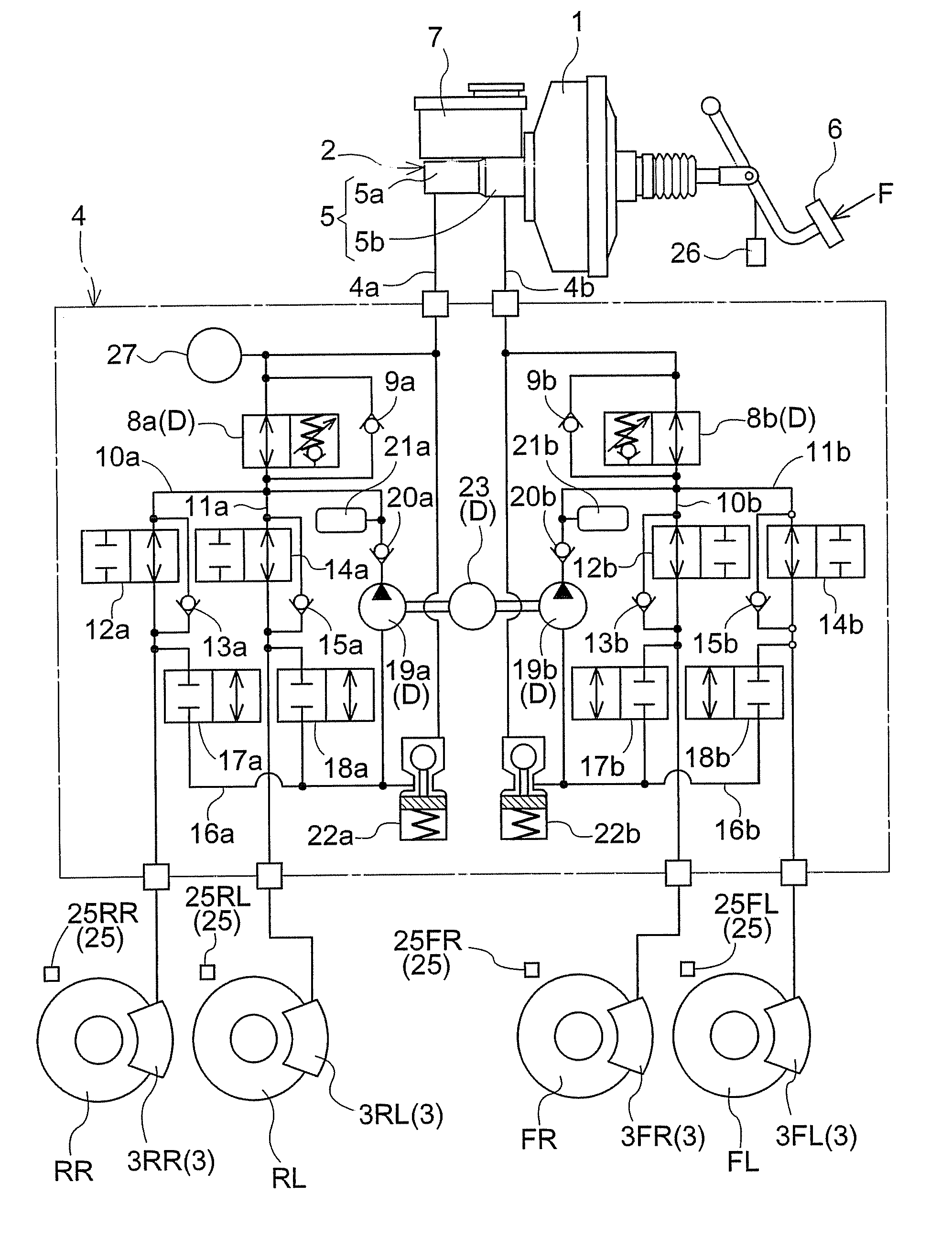
[0037]The braking control device shown in FIG. 1 has a master cylinder 2 for generating a master cylinder hydraulic pressure by amplifying the brake operation force with a booster device 1 and a hydraulic circuit 4 for applying the master cylinder hydraulic pressure to a wheel cylinder 3 of each of the vehicle wheels.

[0038]Four vehicle wheels are provided; i.e., a front right wheel FR, front left wheel FL, right rear wheel RR, and left rear wheel RL. Wheel cylinders 3FR, 3FL, 3RR, and 3RL are provided to each of the vehicle wheels FR, FL, RR, and RL. A hydraulic circuit 4 is configured so that the master cylinder hydraulic pressure generated at the master cylinder 2 is applied to each of the wheel cylinders 3.

[0039]The master cylinder 2 is a tandem-type cylinder having two hydraulic pressure chambers 5. The master cylinder 2 generates a master cylinder hydraulic pressure in each of the two hydraulic pressure chambers 5. A master reservoir 7 is connectedly provided to...

Example

Second Embodiment

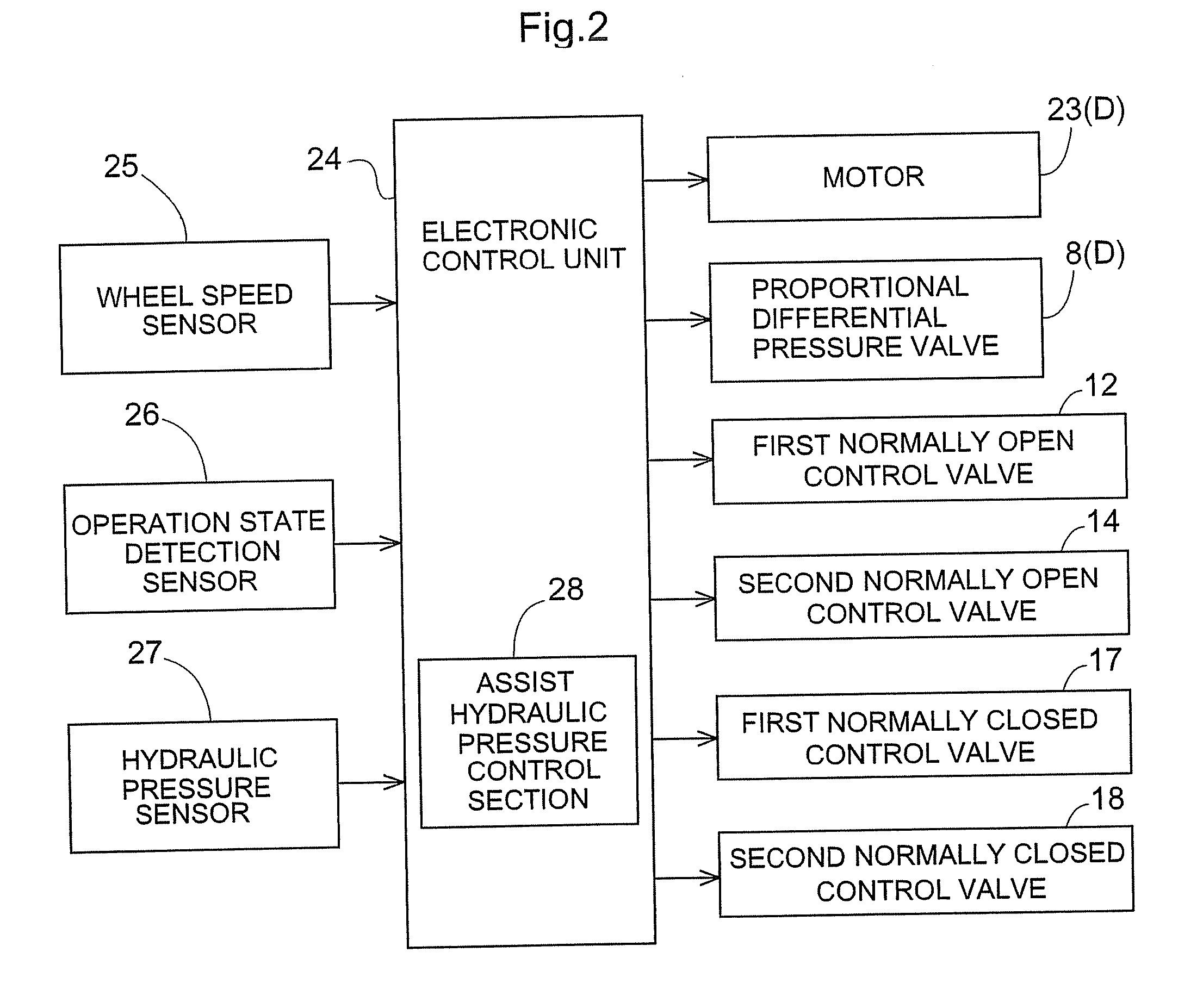
[0088]The second embodiment is another embodiment of a configuration for calculating the assist hydraulic pressure PA in the first embodiment described above. Other constituent components are similar to the first embodiment described above, and descriptions have been omitted.

[0089]A depressing force detection sensor for detecting the depressing force applied to the brake pedal 6 is provided as the brake operation force detection sensor for detecting the brake operation force. This depressing force detection sensor is composed of an operation state detection sensor 26. The depressing force detected by the operation state detection sensor 26 can be directly used as the brake operation force F. Thus, as regards the calculation of the wheel cylinder pressure PWC, as shown in FIG. 3, the assist hydraulic pressure control section 28 calculates the target wheel cylinder pressure PWC from the first correlation extension section S1a, the gradual correlation S4, and the secon...


PUM


Abstract

It is an object of the present invention to minimize any sensation of inadequate firmness and large changes in deceleration rate with respect to a change in a brake operation force when the force exceeds a boost limit point. A first correlation S1 when a brake operation force increases and a second correlation S2 after hysteresis is applied at the time of a decrease in the brake operation force are taken as relationships between a brake operation force F and a wheel cylinder pressure PWC in a state wherein an assist hydraulic pressure PA is not applied. An assist hydraulic pressure control section controls the assist hydraulic pressure PA so that when a brake operation force that exceeds a boost limit point T1 is applied, the assist hydraulic pressure PA is added, hysteresis is applied when the brake operation force decreases, the assist hydraulic pressure PA decreases, and the relationship between the wheel cylinder pressure PWC and the brake operation force F when the assist hydraulic pressure PA decreases to zero becomes the second correlation S2.

Description

BACKGROUND OF THE INVENTION[0001]1. Field of the Invention[0002]The present invention relates to a braking control device having an assist hydraulic pressure control section that adds an assist hydraulic pressure to a master cylinder hydraulic pressure. The pressure is added on the application of a brake operation force that exceeds the boost limit point at which the booster device becomes unable to amplify the brake operation force at the prescribed boost ratio.[0003]2. Description of the Related Art[0004]With the above type of braking control device, the master cylinder generates the master cylinder hydraulic pressure as a result of the force produced as a result of the brake operation force being amplified by a booster device, and the master cylinder hydraulic pressure is applied to each wheel cylinder. However, when the applied brake operation force exceeds the boost limit point at which the booster device becomes unable to amplify the brake operation force at the prescribed boo...

Claims


Application Information

Patent Timeline
IPC IPC(8): G06F19/00B60T8/00B60T13/60B60T13/68
CPCB60T8/442B60T13/141B60T8/4872
Inventor MASUDA, YOSHIONAITO, MASAYUKINIINO, HIROAKI
Owner ADVICS CO LTD
Why Eureka
Try Eureka