Collision detecting device

Inactive Publication Date: 2009-01-22
DENSO CORP
View PDF4 Cites 22 Cited by
  • Summary
  • Abstract
  • Description
  • Claims
  • Application Information

AI Technical Summary

Benefits of technology

[0007]Hereby, a collision detecting device in which a bumper absorber has sufficient ri

Problems solved by technology

However, when the absorber is rigid, the chamber member is deformed only a little in case of collision is caused.
That is, the deformation of the chamber member is limi

Method used


Image

  • Collision detecting device
  • Collision detecting device
  • Collision detecting device

Examples


first embodiment

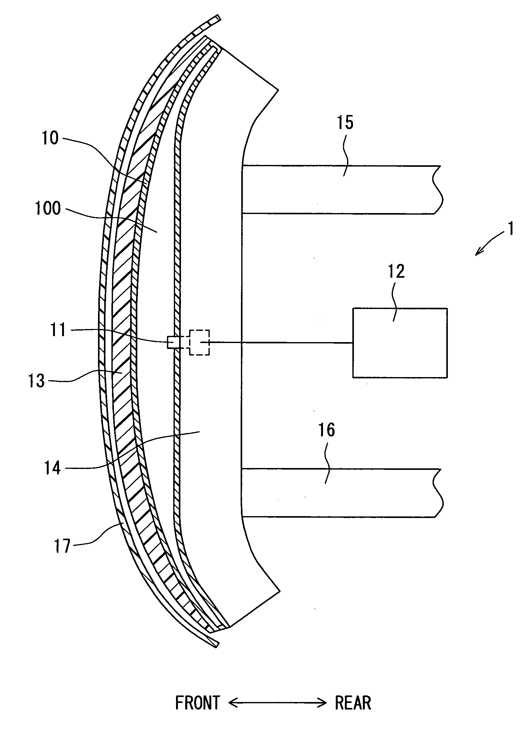
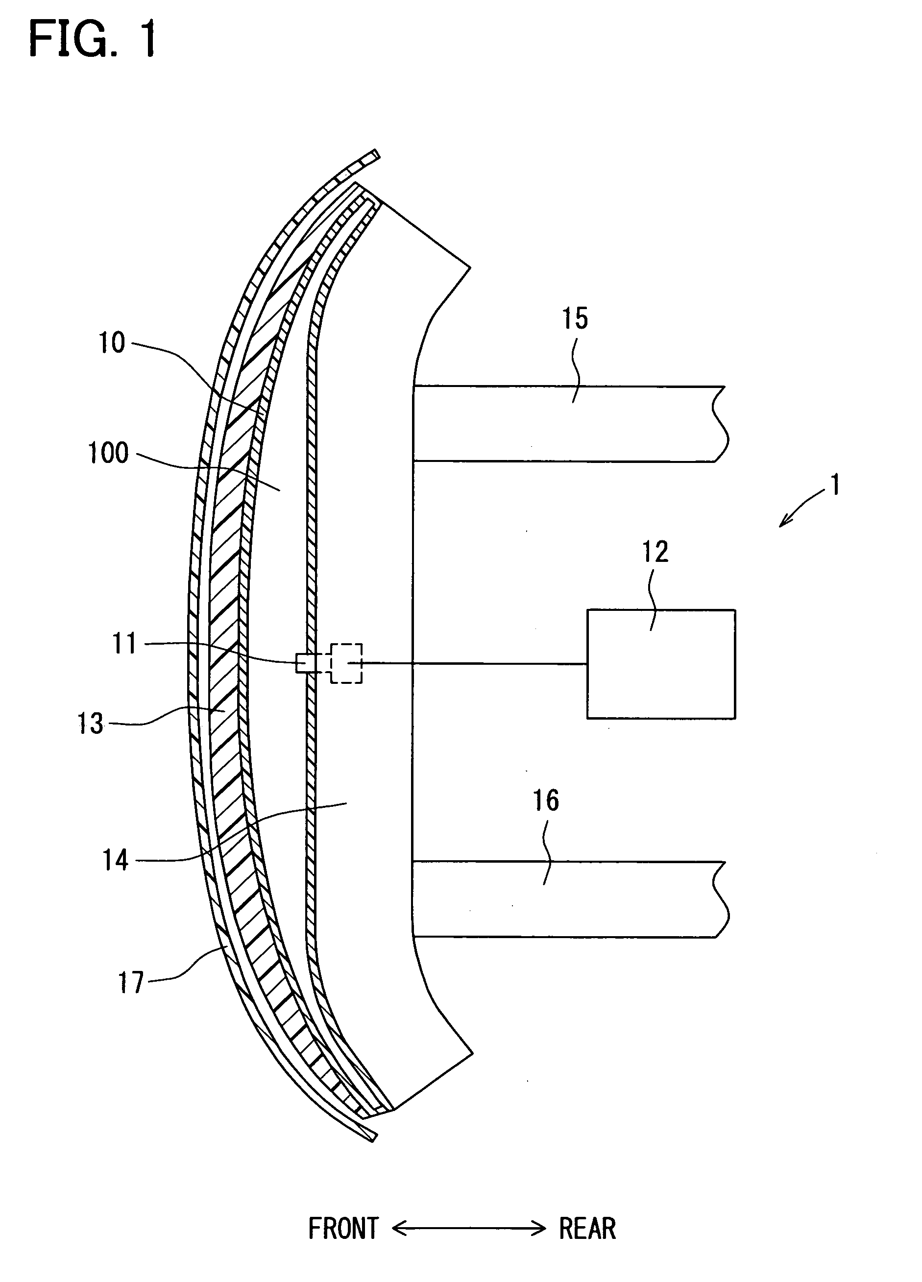
[0028]A structure of a pedestrian collision detecting device for detecting collision with a pedestrian is described with reference to FIG. 1 and FIG. 2.

[0029]As shown in FIGS. 1 and 2, a pedestrian collision detecting device 1 (a collision detecting device) includes a chamber member 10, a pressure sensor 11, a pedestrian collision determination portion 12 and a bumper absorber 13.

[0030]The chamber member 10 is an elongated sack-like member made of such as resin, which has a cross section of a square shape, and provides a chamber 100, which is a sealed space or a substantially sealed space. Air is filled in the chamber 100. The chamber member 10 is arranged on a bumper reinforcement 14 extending in a lateral direction of the vehicle, which has a cross section that substantially two squares are attached in line, so that a rear surface of the chamber member 10 is attached to an upside front surface of the bumper reinforcement 14. The bumper reinforcement 14 is attached to front side en...

second embodiment

[0043]A pedestrian collision detecting device of a second embodiment is described. The second embodiment is a modification of the first embodiment with respect to the structure of the flexible portion.

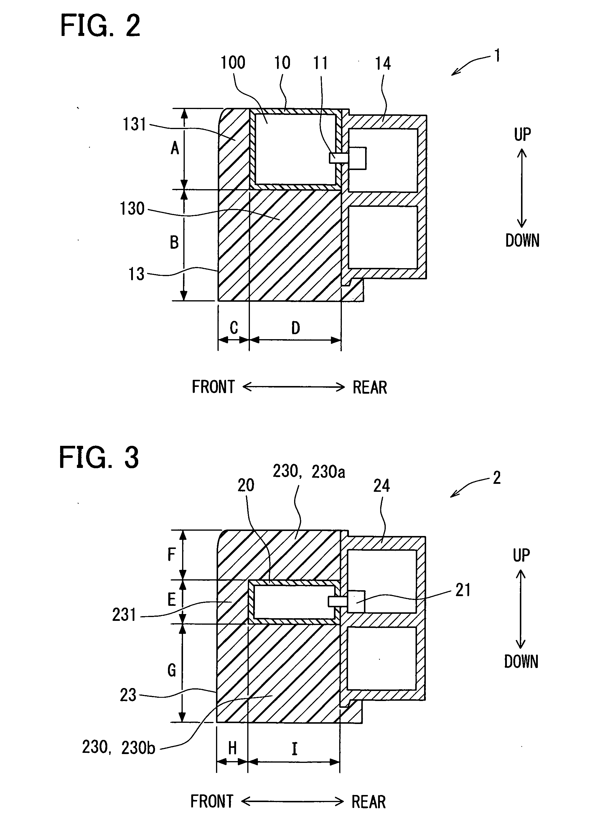
[0044]A structure of the pedestrian collision detecting device is described with reference to FIG. 3. In the second embodiment, only a flexible portion, which has a different structure from the flexible portion of the first embodiment, is described.

[0045]As shown in FIG. 3, a pedestrian collision detecting device 2 (a collision detecting device) includes a chamber member 20, a pressure sensor 21 and a bumper absorber 23.

[0046]The chamber member 20 is an elongated sack-like member made of such as resin. The chamber member 20 has a cross section of a square shape, which is elongated in the front-rear direction. The chamber member 20 is arranged on the bumper reinforcement 24 so that a rear surface of the chamber member 20 is attached to a front surface of the bumper reinforcement 24 at a...

third embodiment

[0051]A pedestrian collision detecting device of a third embodiment is described.

[0052]A structure of the pedestrian collision detecting device is described with reference to FIGS. 4 and 5.

[0053]As shown in FIGS. 4 and 5, a pedestrian collision detecting device 3 (a collision detecting device) includes a chamber member 30, a pressure sensor 31, a pedestrian collision determination portion 32 and a bumper absorber 33.

[0054]The chamber member 30 is an elongated sack-like member made of such as resin, which has a cross section of a square shape and is elongated in the up-down direction. The chamber member 30 provides a chamber 300. Air is filled in the chamber 300. The chamber member 30 is arranged on a bumper reinforcement 34 so that a rear surface of the chamber member 30 is attached to an upside front surface of the bumper reinforcement 34.

[0055]The pressure sensor 31 is connected to the chamber member 30 and detects the pressure inside the chamber 300. The pressure sensor 31 is inc...


PUM


Abstract

A collision detecting device includes a chamber member providing a chamber, a pressure sensor connected to the chamber member, and a bumper absorber absorbing an impact generated by collision of an object with the vehicle. The bumper absorber has a region, which has a thickness in a front-rear direction of the vehicle. The thickness of the region is equal to or smaller than a predetermined thickness. The region is in contact with at least a portion of the chamber member. The collision is detected based on the pressure of the chamber detected by the pressure sensor. Hereby, a collision detecting device in which the bumper absorber has sufficient rigidity, and the chamber has sufficient deformability in case of collision can be obtained.

Description

CROSS REFERENCE TO RELATED APPLICATION[0001]This application is based on Japanese Patent Application No. 2007-186107 filed on Jul. 17, 2007, the disclosure of which is incorporated herein by reference.FIELD OF THE INVENTION[0002]The present invention relates to a collision detecting device for detecting collision of a pedestrian or the like with a vehicle.BACKGROUND OF THE INVENTION[0003]The conventional obstacle determination device for vehicles is disclosed in JP-A-2006-117157 corresponding to US 2006 / 0087417 A1 as a pedestrian collision detecting device for detecting collision of a pedestrian or the like with a vehicle. The obstacle determination device includes an absorber, a pressure sensor, a velocity sensor and an airbag ECU device. The absorber is a member for absorbing an impact generated by collision of an object with a vehicle. The absorber includes a chamber member and a connection member. The chamber member is attached to a front surface of a bumper reinforcement by the...

Claims


Application Information

Patent Timeline
IPC IPC(8): G06F17/00B60R19/48
CPCB60R21/0136B60R19/483
Inventor TANABE, TAKATOSHI
Owner DENSO CORP
Why Eureka
Try Eureka