Sensor Attachment Device, A Sensor and A Light Emitting Device For A Photo-Electrical Sensor

Inactive Publication Date: 2009-01-29
KEYENCE
View PDF5 Cites 11 Cited by
  • Summary
  • Abstract
  • Description
  • Claims
  • Application Information

AI Technical Summary

Benefits of technology

[0015]According to such a configuration, only by the displacement of the operation member to a operational direction after the sensor main body is inserted into the insertion opening with the second regions of the pair of facing surfaces respectively facing toward the external surfaces of the central portions of the pair of locking hooks, the central portions of the pair of locking hooks can be pressed inwardly by the first regions of the pair of facing surfaces, thereby fixing the sensor main body to the holding member. Accordingly, the attachment of the sensor main body is easy in comparison with the conventional configuration in which a nut is screwed onto the sensor main body, then rotated and fastened.
[0016]Further, the tip ends of the pair of locking hooks are locked to the sensor main body to provide a temporary joint by inserting the sensor main body into the insertion opening with the second regions of the pair of facing surfaces respectively facing toward the external surfaces of the central portions of the pair of locking hooks. Alternatively, the tip ends of the pair of locking hooks are locked to the sensor main body to provide a temporary joint, with the pair of facing surfaces between the second regions and first regions facing the external surface of the central portions of the pair of locking hooks, by displacing the operation member to the operational direction after the sensor main body is inserted into the insertion opening. Because the sensor main body can be fixed by operating the operation member in such a state provided with the temporary joint, the sensor main body can be attached stably, thereby suppressing an

Problems solved by technology

However, the above described conventional attachment arrangement of the sensor main body 102 is cumbersome, because it requires inserting the insertion portion 105 of the sensor main body 102 into the opening of the holding member 103, screwing the nut 104 onto the insertion portion 105, and then rotating and fastening the nut 104.
In particular, it becomes significantly cumbersome in such a case where a production line is provided with a number of sensors 101, because the above operations have to be repeat

Method used


Image

  • Sensor Attachment Device, A Sensor and A Light Emitting Device For A Photo-Electrical Sensor
  • Sensor Attachment Device, A Sensor and A Light Emitting Device For A Photo-Electrical Sensor
  • Sensor Attachment Device, A Sensor and A Light Emitting Device For A Photo-Electrical Sensor

Examples


Embodiment Construction

[0035]The present invention will now be described in detail with reference to preferred embodiment and the drawings.

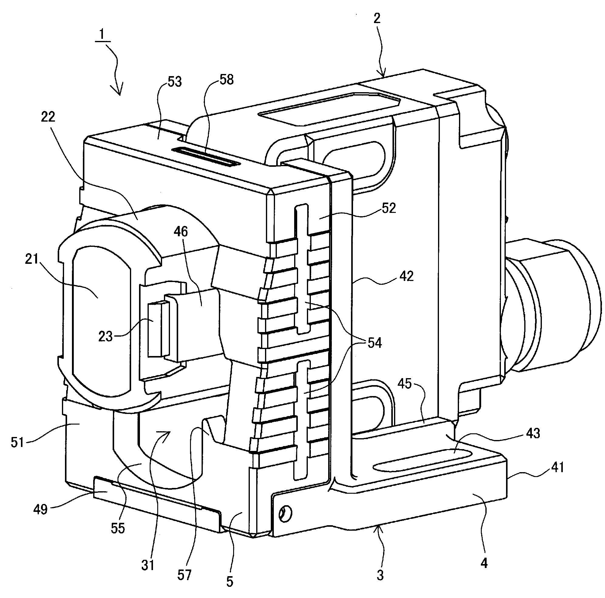
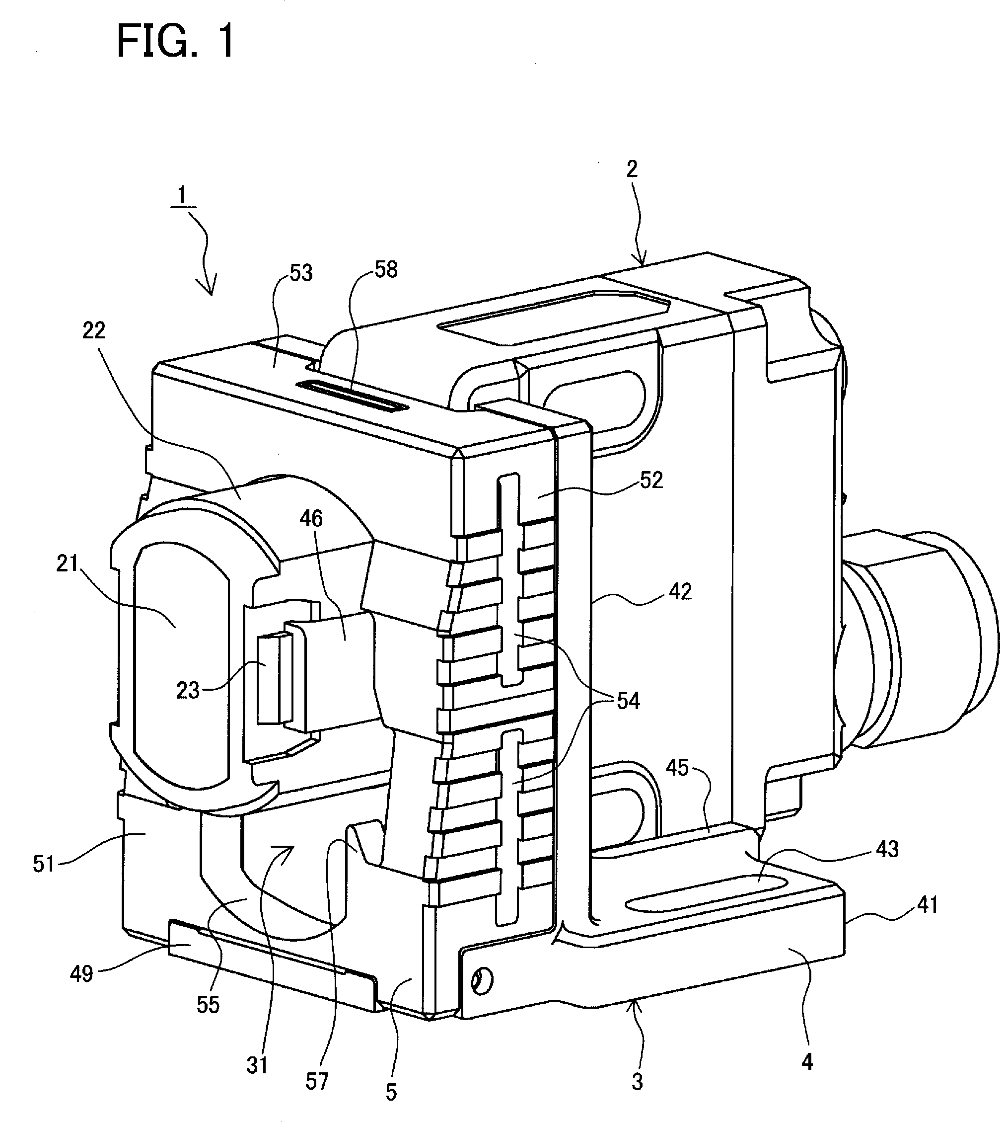
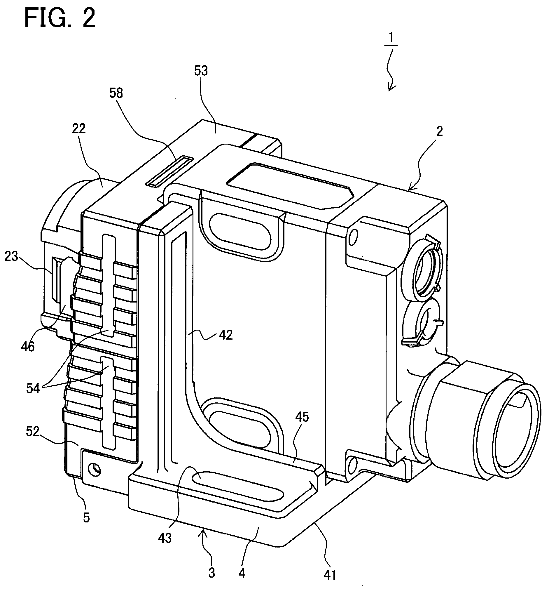
[0036]FIG. 1 is a front perspective view illustrating one example of a photo-electrical sensor 1 according to an embodiment of the present invention. FIG. 2 is a rear perspective view illustrating the photo-electrical sensor 1 of FIG. 1. FIG. 3 is a front elevational view illustrating the photo-electrical sensor 1 of FIG. 1. FIG. 4 is a cross-sectional view taken along a line A-A shown in FIG. 3. FIG. 5 is a front exploded perspective view illustrating the photo-electrical sensor 1 of FIG. 1. FIG. 6 is a rear exploded perspective view the photo-electrical sensor 1 of FIG. 1. FIGS. 7A to 7C illustrate a configuration of a holding member 4, respectively showing a plan view, a front elevational view, and a side elevational view of the holding member 4. FIGS. 8A to 8D illustrate a configuration of an operation member 5, respectively showing a plan view, a front elevational...


PUM


Abstract

This invention provides a sensor attachment device that can be easily attached and detached, a sensor and a light emitting device for a photo-electrical sensor. By downward displacement of an operation member after tip ends of a pair of locking hooks are locked to a sensor main body by inserting the sensor main body into an insertion opening with second regions of a pair of facing surfaces respectively facing toward external surfaces of central portions of the pair of locking hooks, the central portions of the pair of locking hooks can be pressed inwardly by first regions of the pair of facing surfaces, thereby fixing the sensor main body to a holding member. Accordingly, the attachment of the sensor main body is easy in comparison with the conventional configuration in which a nut is screwed onto the sensor main body, then rotated and fastened.

Description

BACKGROUND OF THE INVENTION[0001]1. Field of the Invention[0002]The present invention relates to a sensor attachment device, a sensor and a light emitting device for a photo-electrical sensor, and in particular, to an improvement of an attachment arrangement of a sensor main body and a light emitting device main body.[0003]2. Description of the Related Art[0004]One known method of fixing a sensor such as a photo-electrical sensor is to prepare a threaded sensor main body, attach a nut that is threaded so as to correspond to the thread of the sensor main body, and rotate the nut thereby attaching the sensor main body to a holding member that has been previously fixed to an installation position (refer to, e.g., Japanese Unexamined Utility Model Application Publication No. H7-36339).[0005]FIG. 16 is a perspective view of one example of an attachment arrangement of a sensor main body 102 in a conventional sensor 101. In this example, an almost L-shaped holding member 103 is previously ...

Claims


Application Information

Patent Timeline
IPC IPC(8): G01D21/00G01J1/44
CPCG01D11/24G01J1/02G01J1/0403G01J1/04G01J1/0271
Inventor SUGIYAMA, KAZUTOSHIYAMANE, NORIYOSHI
Owner KEYENCE
Why Eureka
Try Eureka