Crankcase Ventilation System with Pumped Scavenged Oil

Active Publication Date: 2009-01-29
CUMMINS FILTRATION IP INC
View PDF13 Cites 45 Cited by
  • Summary
  • Abstract
  • Description
  • Claims
  • Application Information

AI Technical Summary

Benefits of technology

[0003]The present invention provides another solution to

Problems solved by technology

The pressure differential between the crankcase and the oil outlet of the separator normally ten

Method used


Image

  • Crankcase Ventilation System with Pumped Scavenged Oil
  • Crankcase Ventilation System with Pumped Scavenged Oil
  • Crankcase Ventilation System with Pumped Scavenged Oil

Examples


Embodiment Construction

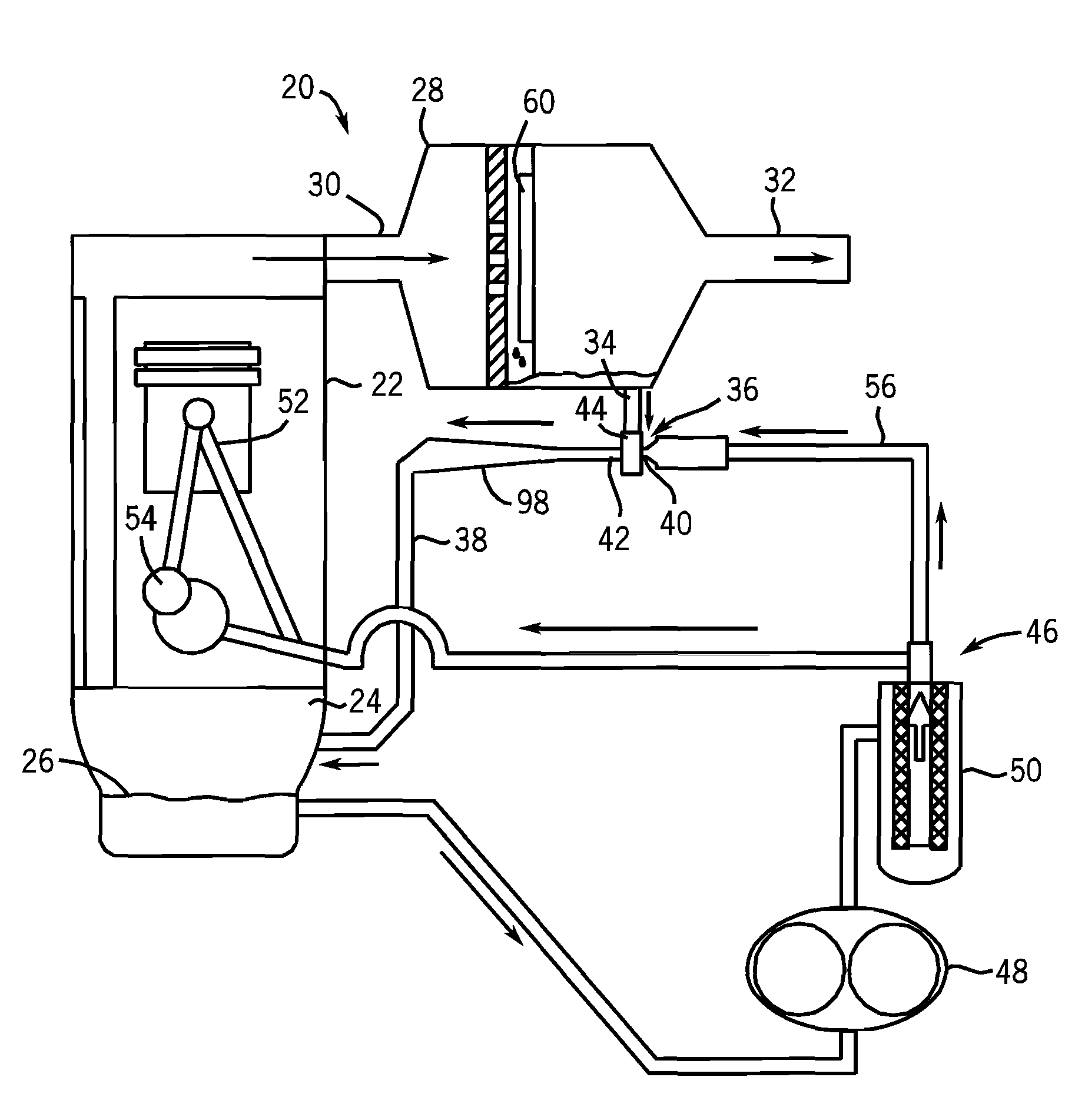
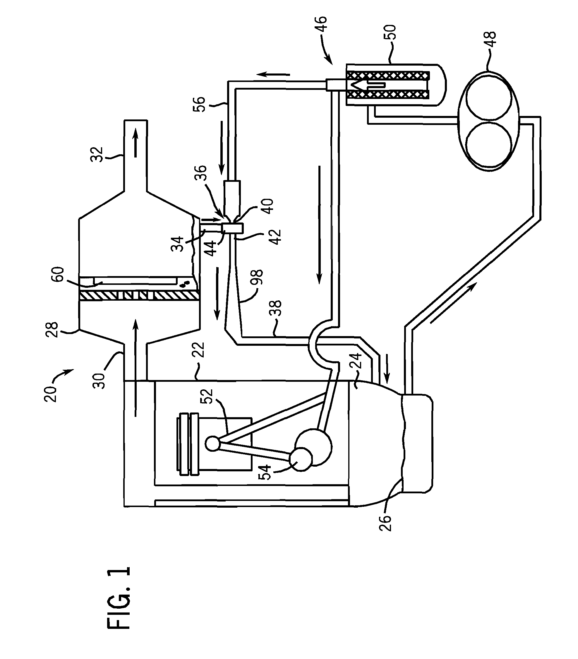
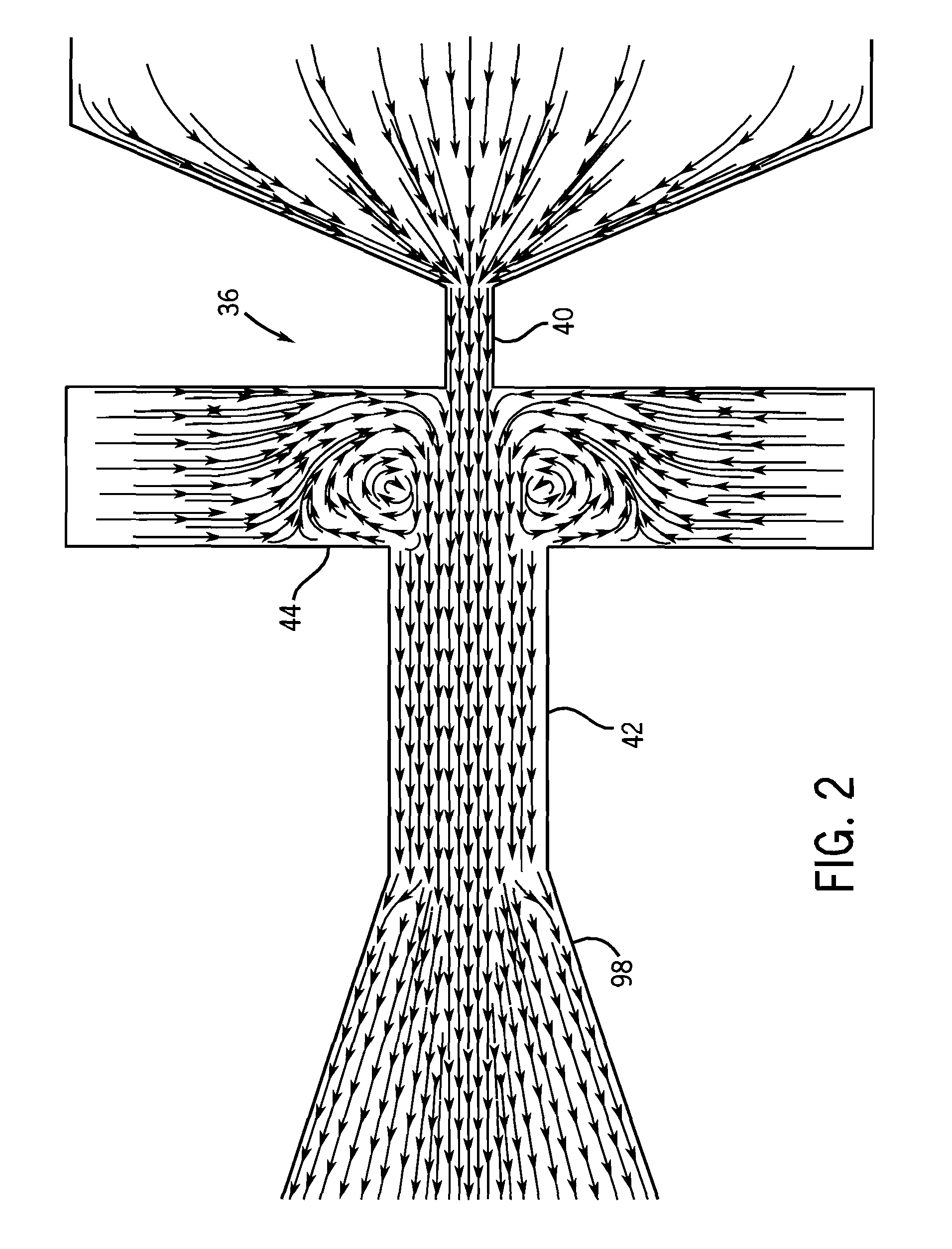
[0011]FIG. 1 shows a crankcase ventilation system 20 for an internal combustion engine 22 generating blowby gas in a crankcase 24 containing engine oil 26 and oil aerosol. The system includes an air / oil separator 28 having an inlet 30 receiving blowby gas and oil aerosol from the crankcase, and having an air outlet 32 discharging clean blowby gas to the atmosphere or returned to the engine air intake, and having an oil outlet 34 discharging scavenged separated oil back to the crankcase, all as is known. In one embodiment air / oil separator 28 is an inertial impactor, for example as in the following incorporated U.S. Pat. Nos. 6,247,463; 6,290,738; 6,354,283; 6,478,109. The system further includes a jet pump 36 pumping scavenged separated oil from oil outlet 34 to crankcase 24. Jet pumps are known in the prior art, for example: “The Design of Jet Pumps”, Gustav Flugel, National Advisory Committee for Aeronautics, Technical Memorandum No. 982, 1939; “Jet-Pump Theory and Performance wit...


PUM

PropertyMeasurementUnit
Pressureaaaaaaaaaa
Flow rateaaaaaaaaaa
Ratioaaaaaaaaaa

Abstract

A crankcase ventilation system for an internal combustion engine has a jet pump suctioning scavenged separated oil from the oil outlet of an air/oil separator and pumping same to the crankcase.

Description

BACKGROUND AND SUMMARY[0001]The invention relates to crankcase ventilation systems for internal combustion engines.[0002]Crankcase ventilation systems for internal combustion engines are known in the prior art. An internal combustion engine generates blowby gas in a crankcase containing engine oil and oil aerosol. An air / oil separator has an inlet receiving blowby gas and oil aerosol from the crankcase, and an air outlet discharging clean blowby gas to the atmosphere or back to the engine air intake, and an oil outlet discharging scavenged separated oil back to the crankcase. The separator has a pressure drop thereacross such that the pressure at its inlet and in the crankcase is higher than the pressure at the separator air outlet and oil outlet. The pressure differential between the crankcase and the oil outlet of the separator normally tends to cause backflow of oil from the higher pressure crankcase to the lower pressure oil outlet. It is known in the prior art to locate the oil...

Claims


Application Information

Patent Timeline
IPC IPC(8): F01M13/04
CPCF01M2013/0438F01M13/04F01M2013/0488F01M2013/0433
Inventor HERMAN, PETER K.CONNOR, MICHAEL J.HOLM, CHRISTOPHER E.HOLZMANN, MARK V.
Owner CUMMINS FILTRATION IP INC
Why Eureka
Try Eureka