Image processor, digital camera, and method for processing image data

a technology of image data and image processor, applied in the field of image processor and digital camera, can solve the problem of inability of digital cameras to confirm whether the detailed portions of displayed images subjected to blurring processing have the desired image quality

Active Publication Date: 2009-01-29
RICOH KK
View PDF9 Cites 88 Cited by
  • Summary
  • Abstract
  • Description
  • Claims
  • Application Information

AI Technical Summary

Benefits of technology

[0028]obtaining high-frequency components in each of the plural regions;
[0029]analyzing the high-frequency components; and
[0030]displaying the synthesized image data and the original image data, w

Problems solved by technology

However, the technologies have a drawback in that it is impossible for the digital cameras to confirm whether the detailed portions of the displayed images subjected to the blurring processing have a desired image qual

Method used


Image

  • Image processor, digital camera, and method for processing image data
  • Image processor, digital camera, and method for processing image data
  • Image processor, digital camera, and method for processing image data

Examples


example 1

[0051]Example 1 of the image processor and digital camera of the present invention will be explained by reference to drawings. FIGS. 3 to 6 are flowcharts for explaining out-of-focus background processing and display of the image having out-of-focus background.

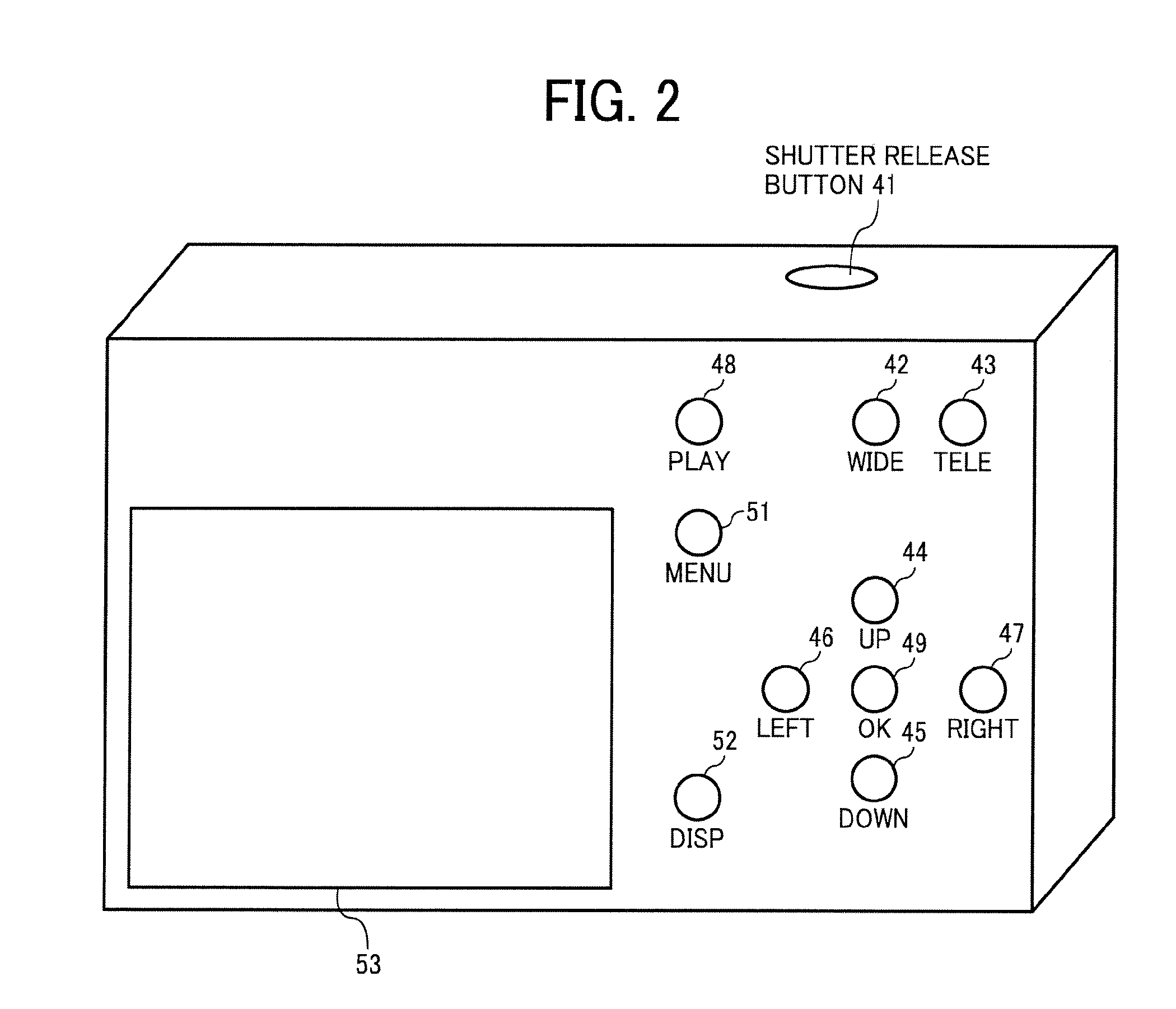
[0052]At first, out-of-focus background processing and display of an image having out-of-focus background in a reproduction mode will be explained. The flow of the processing of from start of reproduction mode to end of the reproduction mode is illustrated in FIG. 3. By pushing the PLAY button 48, the operator can observe the recorded images. In this regard, the status attained by pushing the PLAY button 48 is called reproduction mode. When the reproduction mode is attained, image files, which can be reproduced, are displayed in the displaying device 53. Among the image files, the operator selects an image file to be subjected to an out-of-focus background processing. When the operator pushes the RIGHT button 47, the next imag...

example 2

[0078]In Example 1, a boundary region between the object region and the background region, which has high frequency components, is displayed so that the operator can confirm the effect of the blurring processing. However, it is possible that a portion of the background region, which is suitable for evaluating the effect of the blurring processing, as well as the boundary region, is displayed.

[0079]Specifically, in Example 2, a region including high frequency components in a largest amount is also selected from the entire image to be displayed in the screen so that the operator can well confirm the effect of the blurring processing. Example 2 is the same as Example 1 except that the method for determining the region to be displayed is different.

example 3

[0080]If the image does not have a boundary region to be displayed, which has high frequency components, in Example 1, the following method for determining the region to be displayed is used in Example 3. In this case, a portion of the background region including high frequency components most is displayed in the screen. When-determining the region to be displayed, portions closer to the object region are evaluated faster to determine a portion suitable as the region to be displayed. The evaluation is performed until a portion suitable as the region to be displayed is found.

[0081]Example 3 is the same as Example 1 except that the method for determining the region to be displayed is different.

[0082]As mentioned above, the image subjected to a blurring (out-of-focus) processing is displayed while enlarged in the digital cameral of the present invention, and therefore the effect of the blurring processing can be recognized better than in conventional digital cameras in which only a red...


PUM


Abstract

An image processor including an object extracting device extracting an object region from original image data; an object separating device separating the object region from the other region; a first filter subjecting the object region to out-of-focus filtering processing to output first image data; a second filter subjecting the other region to out-of-focus filtering processing to output second image data; an image synthesizing device synthesizing the first and second image data; a displaying device displaying the synthesized image data and original image data; a region splitting device splitting the synthesized image data into plural regions; a high-frequency component obtaining device obtaining high-frequency components in each of the plural regions; a high-frequency component analyzing device analyzing the high-frequency components; and a zooming device zooming a region among the plural regions having higher frequency components.

Description

BACKGROUND OF THE INVENTION[0001]1. Field of the Invention[0002]The present invention relates to an image processor and a digital camera, which can easily confirm whether an out-of-focus processing (hereinafter sometimes referred to as a blurring processing) is performed. In addition, the present invention also relates to a method for processing image data.[0003]2. Discussion of the Related Art[0004]Published unexamined Japanese patent application No. (hereinafter referred to as JP-A) 2005-229326 discloses a technology concerning cameras and through image displaying methods such that an image, which has been subjected to an image processing such as white balance processing, is displayed in a region while the original image is displayed in another region so that the user can compare the processed image with the original image.[0005]In addition, another technology is proposed in that a blurring processing, which is similar to the above-mentioned blurring processing and to blurring pro...

Claims


Application Information

Patent Timeline
IPC IPC(8): H04N5/225
CPCH04N1/4092
Inventor KANEHIRO, MAKOTO
Owner RICOH KK
Why Eureka
Try Eureka