
System and Method for Frequency Pushing/Pulling Compensation

a frequency pushing/pulling compensation and compensation system technology, applied in the field of electronic circuit systems and methods, can solve the problems of oscillators without tuning being subject to frequency pushing/pulling, oscillator operational contamination, frequency pushing/pulling, etc., and achieves the effects of less expensive, reliable, and simple design

Active Publication Date: 2009-10-29
TEXAS INSTR INC
View PDF0 Cites 26 Cited by
  • Summary
  • Abstract
  • Description
  • Claims
  • Application Information

AI Technical Summary

Benefits of technology

[0013]An advantage of an embodiment is that the design of an analog portion of a power management system and of the oscillator may be relaxed. This may enable a simpler design that may be less expensive, more reliable, smaller, and so forth.
[0014]A further advantage of an embodiment is that expensive frequency pushing / pulling compensation techniques requiring electrical isolation, high performance components, and so forth may no longer be needed. This may lead to a simpler design that is less expensive, smaller, more reliable, and so forth.
[0015]Yet another advantage of an embodiment is that it may be adaptable to a range of aggressors causing frequency pushing / pulling. Therefore, a single embodiment may be able to mitigate frequency pushing / pulling from a number of different aggressor types, rather than utilizing multiple frequency pushing / pulling mitigation techniques, each of which may potentially be capable of only reducing frequency pushing / pulling from a small number of aggressor types.

Problems solved by technology

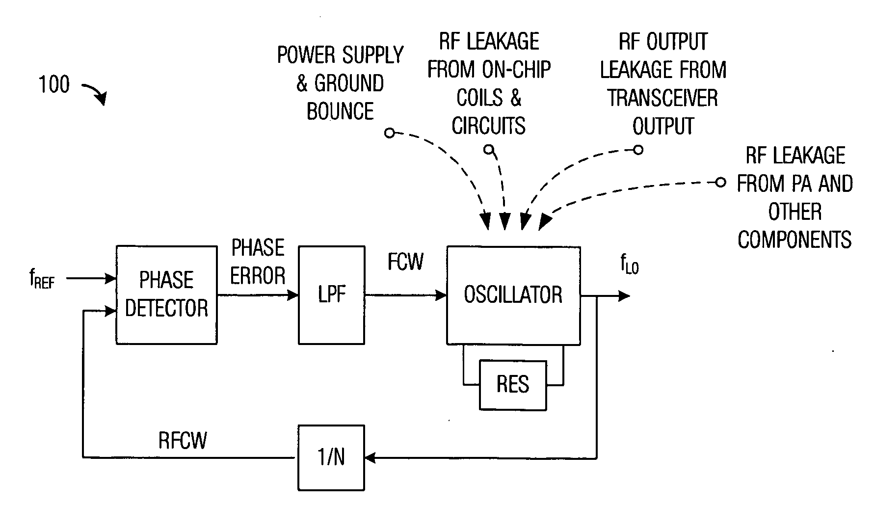
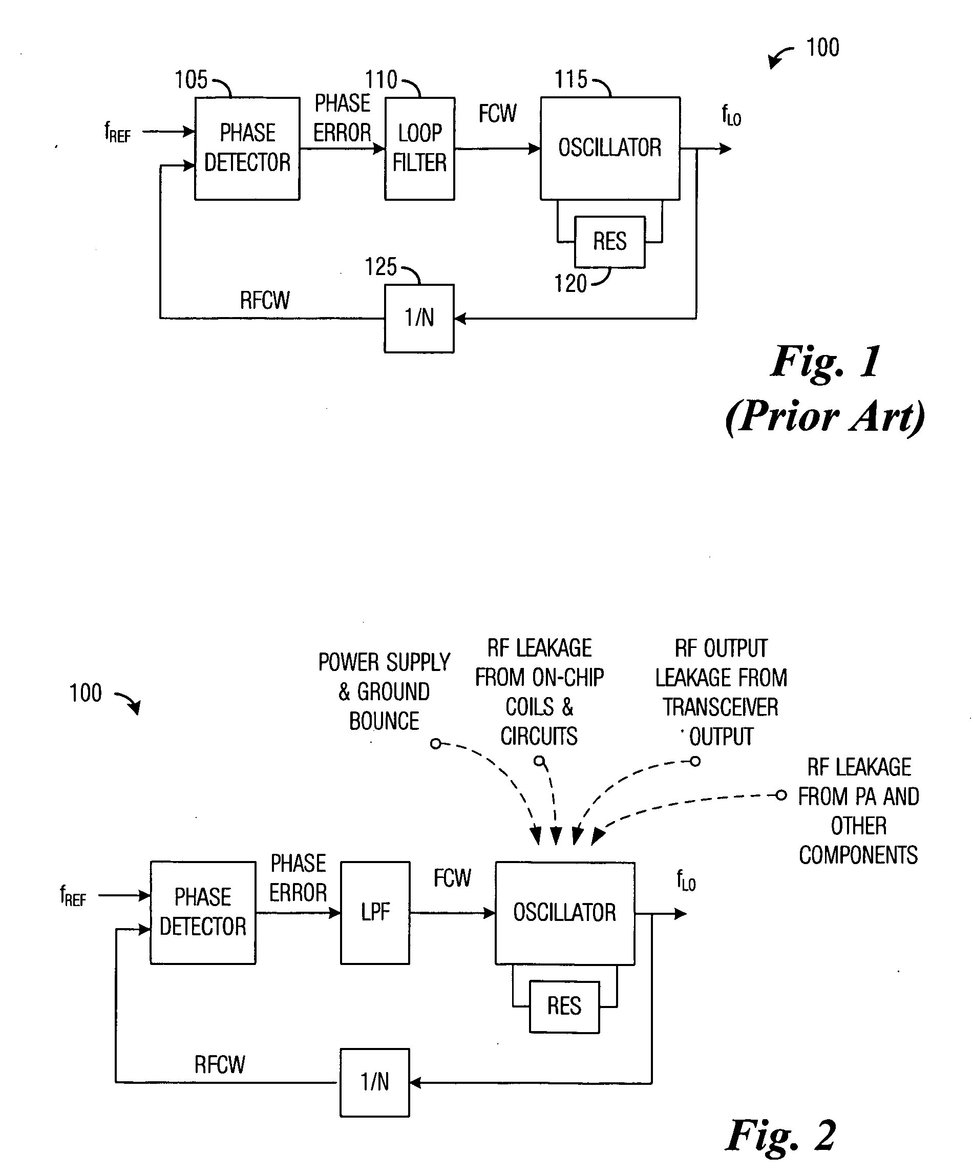
The oscillator operational contamination may typically be due to frequency pushing / pulling of an oscillator core.
Such artifacts present in the supply voltage or electrical ground may be caused by a number of factors, including but not limited to: a current rush caused by other circuits operating in a general vicinity, electrical ground contamination due to wiring and bonding resistances and parasitics, and so forth.
For example, frequency pushing / pulling may be a problem in a digitally controlled oscillator (DCO) that implements a capacitance of a tank circuit with segmented banks of capacitors controlled by a digital engine, such as an all-digital PLL (ADPLL).
Even oscillators without tuning may be subject to pushing / pulling since they may also be subject to the aggressors like tunable oscillators.
As an example, when a transmitter's output power changes, the power supply may not be able to filter out the sudden change in the supply voltage and as a result, the oscillator's frequency may jump instantaneously.
However, the transmitter's error vector magnitude (EVM), root mean square (RMS) and peak phase error, as well as spectrum may be severely degraded while the ADPLL recovers.

Method used


Image

  • System and Method for Frequency Pushing/Pulling Compensation
  • System and Method for Frequency Pushing/Pulling Compensation
  • System and Method for Frequency Pushing/Pulling Compensation

Examples


Embodiment Construction

[0041]The making and using of the embodiments are discussed in detail below. It should be appreciated, however, that the present invention provides many applicable inventive concepts that can be embodied in a wide variety of specific contexts. The specific embodiments discussed are merely illustrative of specific ways to make and use the invention, and do not limit the scope of the invention.

[0042]The embodiments will be described in a specific context, namely a wireless communications device adherent to a 2G or 3G cellular communications standard, such as Enhanced Data for GSM Evolution (EDGE), Wideband Code Division Multiple Access (WCDMA), Bluetooth-Enhanced Data Rate (BT-EDR), Wireless Local Area Network (WLAN), Worldwide Interoperability for Microwave Access (WiMAX), Long-Term Evolution (LTE), and so forth. The invention may also be applied, however, to other wireless communications devices adherent to other cellular communications standards, as well as to wireless transmitters...


PUM


Abstract

A system and method for frequency pushing / pulling compensation in phase-locked loops including a method for cancelling frequency push / pull in an oscillator of a transmitter. The method includes computing an error signal from a signal of a phase locked loop, wherein the error signal includes an aggressor signal. Transfer characteristics are computed for the aggressor signal. A transmitted signal is filtered using the transfer characteristics to produce a correction term. The correction term is applied to a frequency control word being provided to the oscillator.

Description

[0001]This application claims the benefit of U.S. Provisional Application No. 61 / 047,619, filed Apr. 24, 2008, entitled “A Method and Apparatus of Compensating an ADPLL from Frequency Pushing,” which application is hereby incorporated herein by reference.TECHNICAL FIELD[0002]The present invention relates generally to a system and method for electronic circuits, and more particularly to a system and method for frequency pushing / pulling compensation in phase-locked loops (PLL).BACKGROUND[0003]The oscillation stability of a voltage controlled oscillators (VCO) may be perturbed by a number of aggressors present in their operational vicinity. The oscillator operational contamination may typically be due to frequency pushing / pulling of an oscillator core. To differentiate between the two (pushing and pulling), oscillator pushing may be categorized to be a change in the oscillator caused by changes in a supply voltage and / or electrical ground. Such artifacts present in the supply voltage o...

Claims


Application Information

Patent Timeline
IPC IPC(8): H04B1/38H04B1/04
CPCH03L2207/50H03L7/099
Inventor WAHEED, KHURRAMMUHAMMAD, KHURRAMZHUANG, JINGCHENG
Owner TEXAS INSTR INC
Learn More