Machined window undercut

a technology of window undercutting and machined window, which is applied in the direction of casings/cabinets/drawers, casings/cabinets/drawers, instruments, etc., can solve the problems of unsatisfactory users, thin outer structures that cannot offer enough support to protect internal components, and the weight and thickness of electronic devices can be reduced, so as to and reduce the overall thickness and weight of electronic devices. , the effect o

Inactive Publication Date: 2008-03-13
APPLE INC
View PDF12 Cites 29 Cited by
  • Summary
  • Abstract
  • Description
  • Claims
  • Application Information

AI Technical Summary

Benefits of technology

[0007]A trend exists in the computer industry to reduce size, weight and thickness of electronic devices. Typically, any computer part that can be made smaller is made smaller to accommodate this trend. By way of example, the wall thickness of the computer housing has been made thinner over the years. In most instances, decreased wall thickness reduces the overall thickness and weight of the computer, both of which are desired to make a portable computer more portable.

Problems solved by technology

Nevertheless, making the outer structure thinner to reduce computer weight and thickness has its drawbacks.
Consequently, the thinner outer structure can not offer enough support to protect the internal components of the computer.
Even when the thinner outer structure is strong enough to protect the internal components, users who have come to expect rigid structures can be unsatisfied.
Moreover, recently, computer housing designs have been implemented in more complex shapes.
These complex designs can create structural problems that result in even more flexible outer shells.
The complex shapes can be contoured or curvilinear, which generally reduces the overall strength of the computer housing.
The complex shapes also make it increasingly difficult to provide any internal support to offset these problems.

Method used


Image

  • Machined window undercut
  • Machined window undercut
  • Machined window undercut

Examples


Embodiment Construction

[0032]The present invention will now be described in detail with reference to a few preferred embodiments thereof as illustrated in the accompanying drawings. In the following description, numerous specific details are set forth in order to provide a thorough understanding of the present invention. It will be apparent, however, to one skilled in the art that the present invention can be practiced without some or all of these specific details. In other instances, well known process steps have not been described in detail in order not to unnecessarily obscure the description of the present invention.

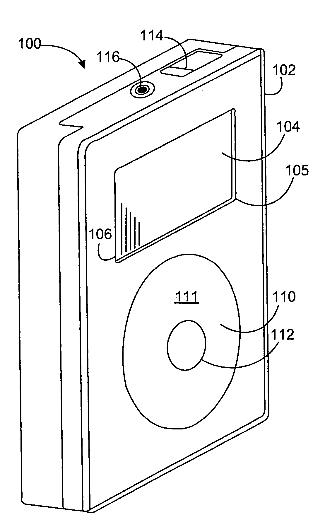
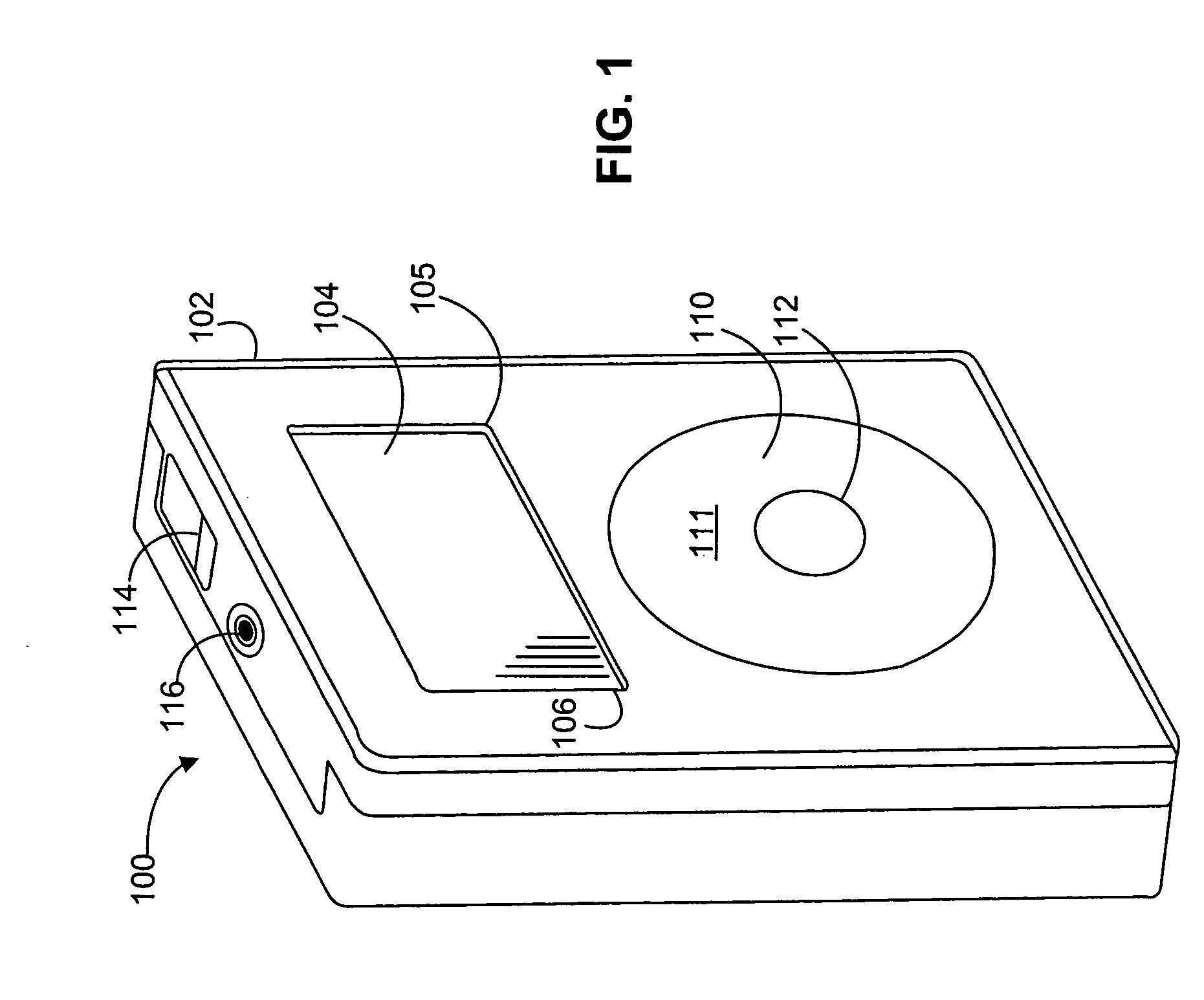
[0033]FIG. 1 is a perspective diagram of a media player 100, in accordance with one embodiment of the present invention. The term “media player” generally refers to computing devices that are dedicated to processing media such as audio, video or other images, as for example, music players, game players, video players, video recorders, cameras, and the like. In some cases, the media players...


PUM


Abstract

A media player comprising a display screen is provided. The media player can include a housing having an opening and an area of reduced thickness around the opening. The media player can also include a transparent wall having a flange. Alternatively, the transparent wall may not require a flange but rather can be a flat, substantially transparent piece of material such as plexiglass or glass. The flange can be adhered to a surface of the area of reduced thickness in order to form a transparent protective cover for the display screen. In another embodiment of the invention, a method is provided. The method can include forming a transparent wall having a stepped edge for placing in an opening of a media player. The method can also include adhering an adhesive to at least one surface of the stepped edge of the transparent wall. The method can include as well using the cutting tool to cut away a portion of the underside of a housing that surrounds an opening in a media player. The method can also include adhering the transparent wall to the housing using the adhesive.

Description

BACKGROUND OF THE INVENTION[0001]This invention can relate to methods that improve construction of electronic devices. More specifically, this invention can relate to improving the efficiency of an electronic device stored in a closed-back housing.[0002]As products compete to be thinner and thinner, it is important to be as space efficient as possible both to make room for other components as well as to improve and ease the assembly process as much as possible.[0003]In conventional closed-back products, the window normally sits flat on the interior of the housing surface, so no space is saved. More specifically, the window flange simply sits on top of the housing's inner surface.[0004]Therefore, it would be desirable to increase the volume available for storing components in an electronic device without increasing the device size.[0005]It would also be desirable to increase the volume available for components in a closed-back electronic device.[0006]It would be yet further desirable...

Claims


Application Information

Patent Timeline
Patent Type & Authority Applications(United States)
IPC IPC(8): H04R1/02H05K5/00
CPCH04R1/02H04R5/00H05K5/0239Y10T156/1064Y10T156/1082Y10T156/1059Y10T156/1066Y10T156/1062H05K5/03
Inventor WEBER, DOUGLAS J.MOOLSINTONG, PINIDA JANZADESKY, STEPHEN P.
Owner APPLE INC
Why Eureka
Try Eureka