

Image forming device
- Summary
- Abstract
- Description
- Claims
- Application Information
AI Technical Summary
Benefits of technology
Problems solved by technology
Method used
Image

Examples
Embodiment Construction
[0039]Embodiments of the present invention are described hereafter with reference to the drawings.
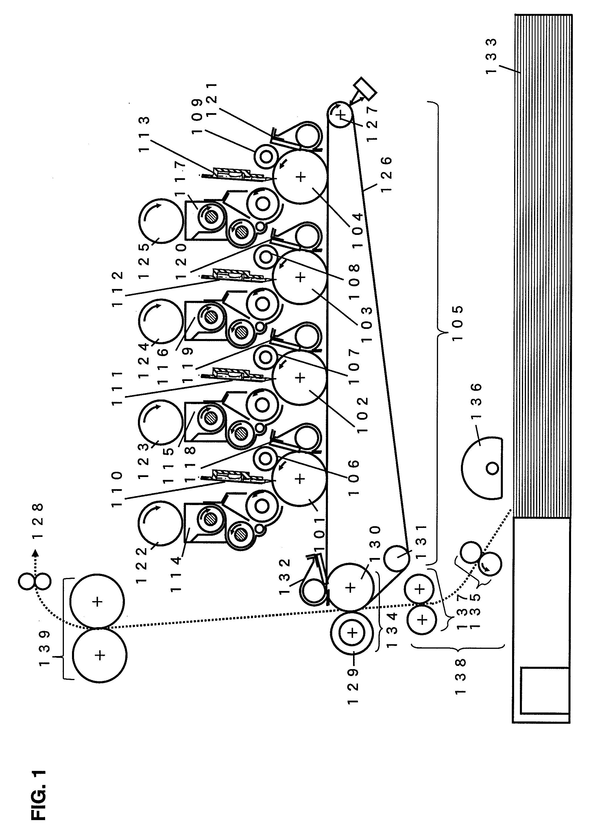
[0040]FIG. 1 shows the structure of a color image forming apparatus using the exposure device according to an embodiment of the present invention.
[0041]In FIG. 1, four image forming bodies or photosensitive bodies 101, 102, 103, and 104 and a transfer unit 105 extended over them are shown. Charging devices 106, 107, 108, and 109, exposure devices 110, 111, 112, and 113, developing devices 114, 115, 116, and 117, photosensitive body cleaning devices 118, 119, 120, and 121 are provided around the photosensitive bodies 101, 102, 103, and 104, respectively.
[0042]Developing agent storages 122, 123, 124, and 125 store the corresponding color toners to the developing devices 114, 115, 116, and 117, respectively. The stored toners are supplied to the developing devices 114 to 117 in the manner that the image recorded on paper has a nearly uniform density.
[0043]The transfer unit 105 comprises a ...
PUM
 Abstract
Description
Claims
Application Information