
Microfluidic devices and methods

a microfluidic device and microfluidic technology, applied in the direction of fluid speed measurement, burettes/pipettes, additive manufacturing apparatus, etc., can solve the problems of low sensitivity, limited range of proteins that can be analyzed, and conventional 2d-page technology

Inactive Publication Date: 2009-01-29
ZYOMYX
View PDF15 Cites 20 Cited by
  • Summary
  • Abstract
  • Description
  • Claims
  • Application Information

AI Technical Summary

Benefits of technology

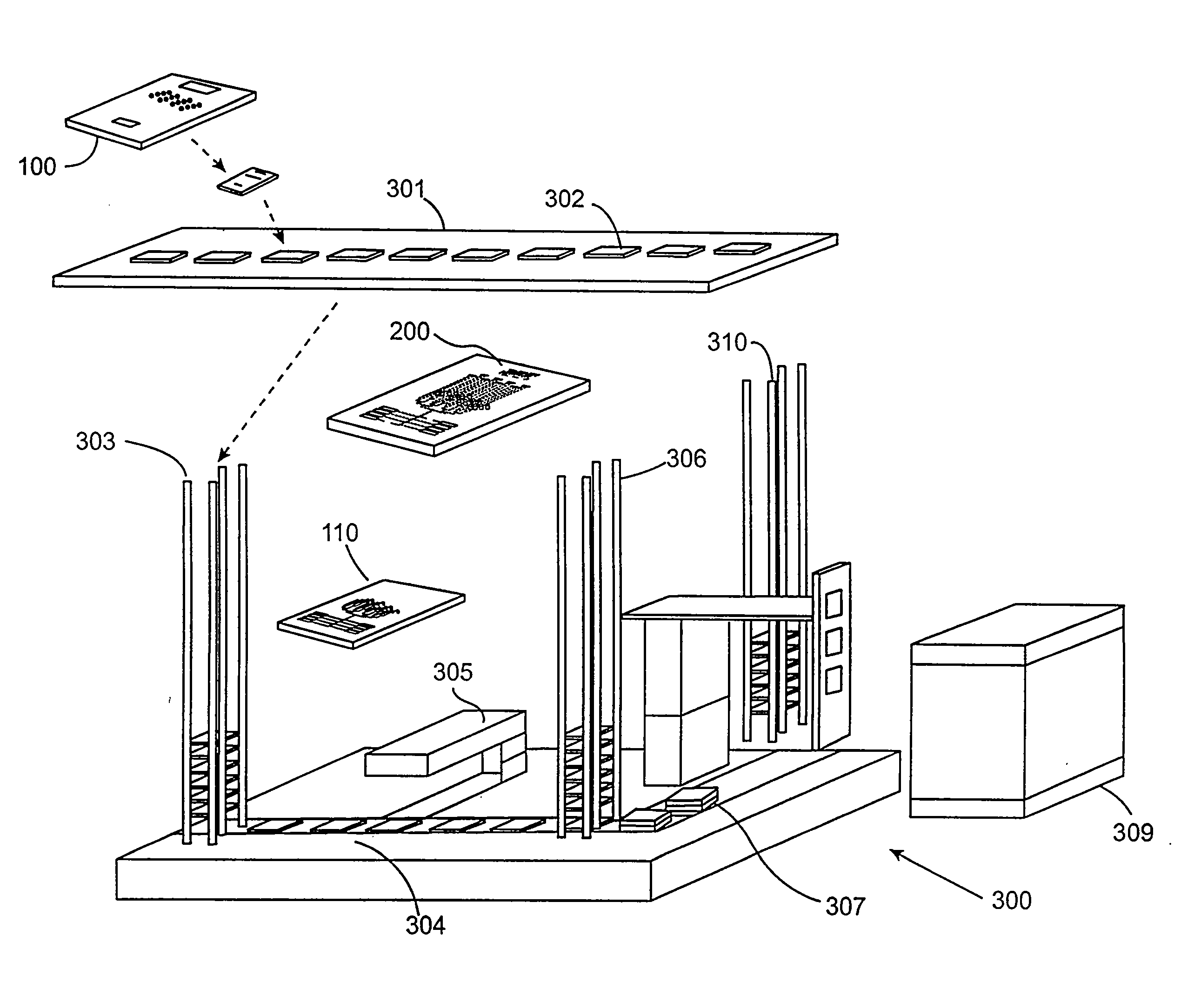
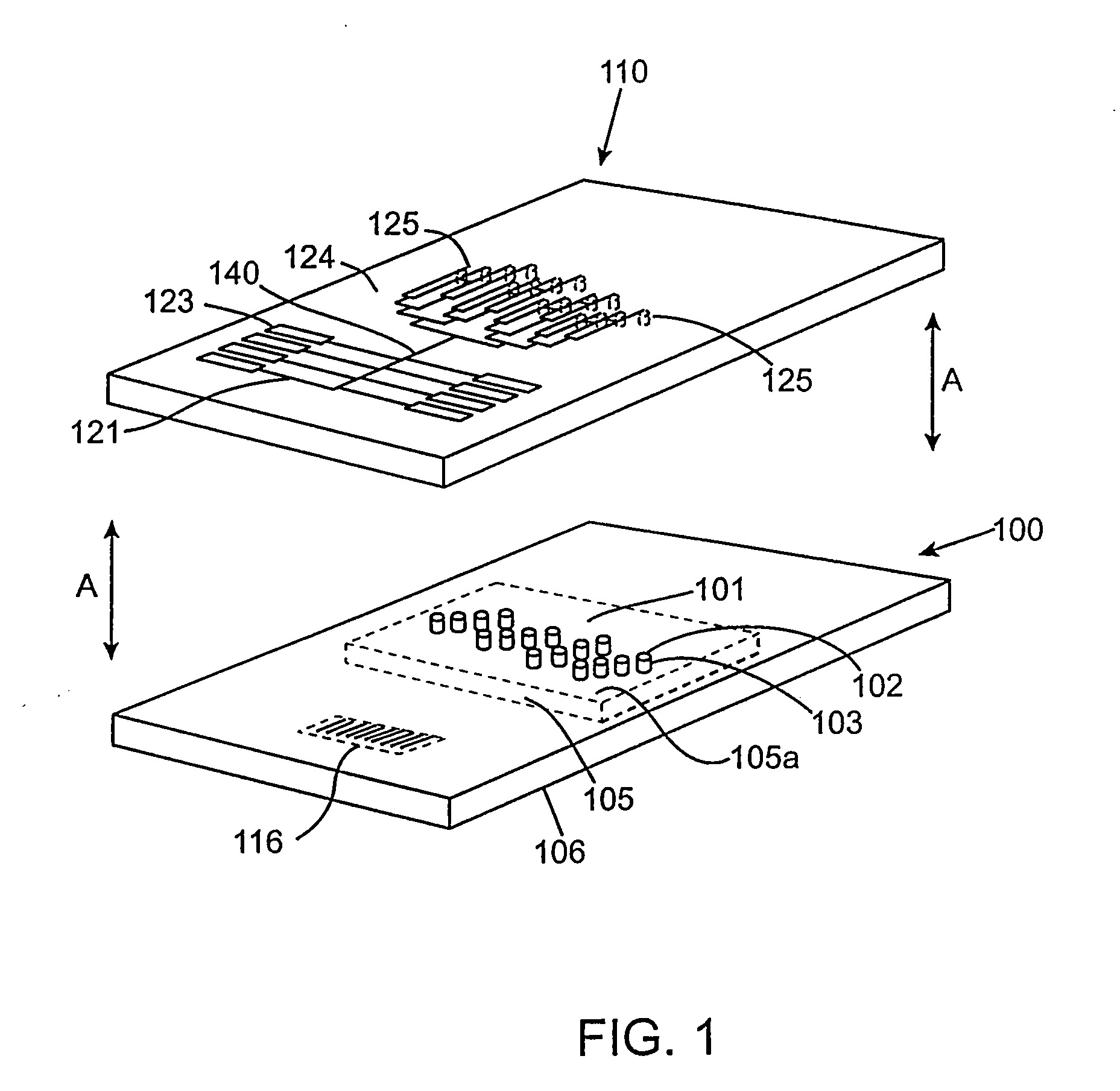
"The invention is a microanalysis chip with a transfer-separation channel that can receive a sample and process it using reagents. The chip can also have a dispenser chip that can deposit liquid samples onto the sample surface and bind the analytes for further processing. The invention also includes a method for chemically affecting a sample by inserting a pillar into the transfer-separation channel and passing a reagent fluid through it. The invention also includes an analysis system comprising a microanalysis chip and a sample chip connected to an analysis device. The technical effects of the invention include improved efficiency in processing samples and reduced reagent consumption."

Problems solved by technology

Conventional 2D-PAGE technology, however, has a number of drawbacks.
Drawbacks include low sensitivity (e.g., 1 ng protein detection limit with silver staining), the limited range of proteins that can be analyzed, (membrane proteins, high molecular, low molecular proteins are underrepresented), and low sample throughput.
The low sample throughput is due to the labor and time intensiveness of this method.
Besides being complex and costly, these automated systems are not generally suited to identify low abundance proteins.
However these methods have limitations including low detection limits and the limited scope of proteins that may be analyzed (e.g., due to solution condition limitations imposed by the selected chromatographic method).

Method used


Image

  • Microfluidic devices and methods
  • Microfluidic devices and methods
  • Microfluidic devices and methods

Examples


Embodiment Construction

[0043]Embodiments of the invention find utility in the post-genome era of functional genomics or proteomics to decipher the complex interplay among various biological molecules (e.g., genes, gene products, metabolites, proteins) in biological systems. They utilize array type devices for analyte isolation along with microfluidic devices that may have micropurification capability. The strengths of array-type devices and the strengths of microfluidic type devices may be combined to perform multiple processes in parallel and in an integrated manner.

[0044]In commercial settings, embodiments of the invention may be used in the pharmaceutical industry for, e.g., proteomic studies. Using embodiments of the invention, potential drug candidates can be discovered or can be verified as being therapeutic. Embodiments of the invention may also be used as diagnostic tools in a clinical setting for staging or disease progression. They may find use in environmental analyses to track and identify con...


PUM

PropertyMeasurementUnit
aspect ratioaaaaaaaaaa
heightaaaaaaaaaa

Abstract

Embodiments of the invention are directed to microfluidic devices. In one embodiment, a microanalysis chip comprises a body having at least one transfer-separation channel with a channel bottom that has a bottom opening. The transfer-separation channel terminates in a discharge aperture.

Description

CROSS-REFERENCES TO RELATED APPLICATIONS[0001]This application claims the benefit of U.S. provisional patent application Nos. 60 / 184,381 filed Feb. 23, 2000 and 60 / 225,999 filed Aug. 16, 2000. This application is also being filed on the same day as U.S. non-provisional application Ser. No. ______ entitled “Chips With Elevated Sample Surfaces” by Pierre F. Indermuhle et al. (Attorney Docket No. 020144-000810). All of the above provisional and non-provisional patent applications are herein incorporated by reference in their entirety for all purposes and are all assigned to the same assignee as the present application.BACKGROUND OF THE INVENTION[0002]Conventional methods for performing high throughput mass spectrometric (MS) protein identification employ either 2D-PAGE technology or various modes of multidimensional chromatography. 2D-PAGE is commonly used in proteomics (i.e., the study of proteins). In a typical 2D-PAGE process, 3000 to 5000 different proteins can been separated. Afte...

Claims


Application Information

Patent Timeline
Patent Type & Authority Applications(United States)
IPC IPC(8): B01J19/00B01L3/00B01L3/02G01N33/53B01L99/00B81B1/00C40B40/10C40B60/14G01N35/04G01N35/10G01N37/00
CPCB01J19/0046Y10T436/118339B01J2219/00351B01J2219/00367B01J2219/00369B01J2219/00382B01J2219/00497B01J2219/00504B01J2219/00509B01J2219/00585B01J2219/00587B01J2219/00596B01J2219/00605B01J2219/0061B01J2219/00612B01J2219/00619B01J2219/00621B01J2219/00626B01J2219/00637B01J2219/00641B01J2219/00644B01J2219/00664B01J2219/00677B01J2219/00702B01J2219/00725B01L3/0241B01L3/0244B01L3/0248B01L3/0262B01L3/5085B01L3/5088B01L2300/0809B01L2300/0848B01L2400/022B01L2400/0688B82Y30/00C40B40/10C40B60/14Y10T436/114165Y10T436/25Y10T436/2575Y10T436/11Y10T436/255Y10T436/117497Y10T436/25375Y10T436/143333Y10T436/156666B01J2219/00317B33Y80/00C12Q1/00
Inventor JEDRZEJEWSKI, PAULNOCK, STEFFENWAGNER, PETERINDERMUHLE, PIERREZAUGG, FRANK G.
Owner ZYOMYX
Learn More