Coin feeding apparatus and method for biasing a release of coins

a coin feeding and coin release technology, applied in coin counters, coin/paper handlers, instruments, etc., can solve the problems of coin inadvertent drop off claw, coin unintentionally striking the slit-shaped exit obliquely, and inability to effectively feed so as to achieve effective pushed out, effective fed into the coin opening, and stable feeding

Active Publication Date: 2009-01-29
ASAHI SEIKO CO LTD
View PDF7 Cites 9 Cited by
  • Summary
  • Abstract
  • Description
  • Claims
  • Application Information

AI Technical Summary

Benefits of technology

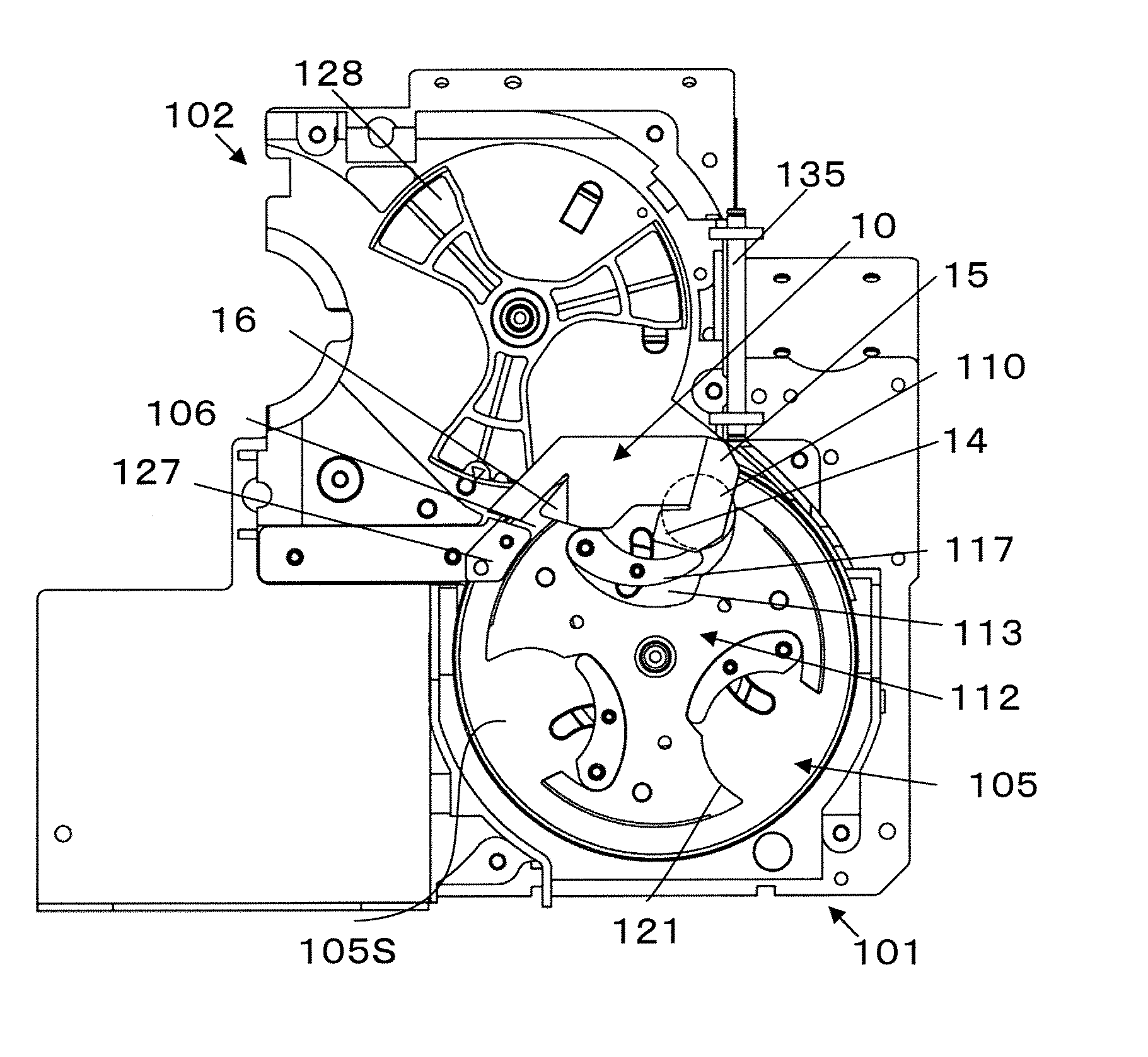
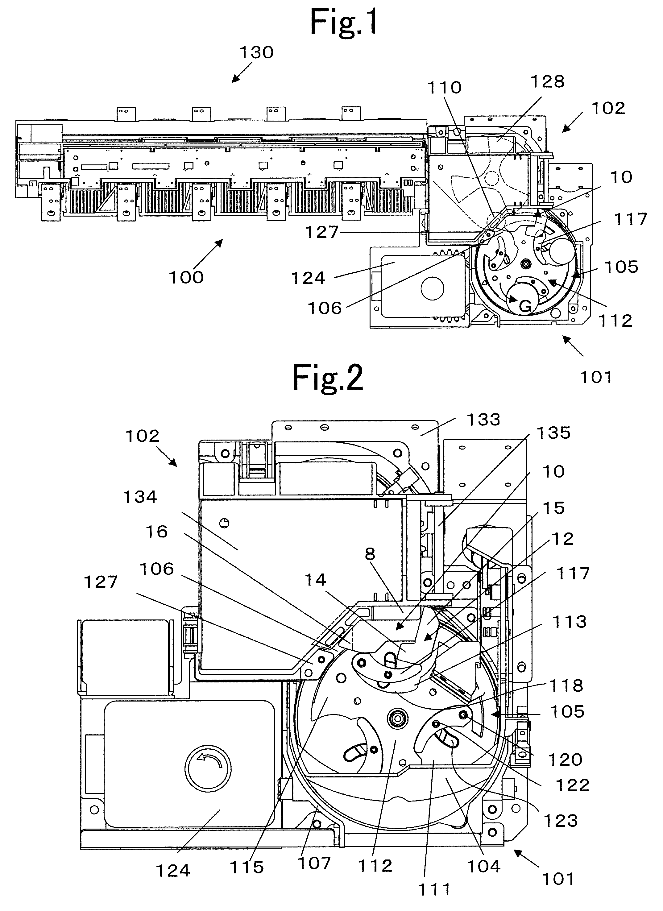
[0012]It is a first object of the present invention to provide a coin feeding apparatus that is capable of efficiently processing a coin by providing apparatus for maintaining and carrying a coin in a more stable controlled state when the coin is being fed by a high speed rotation disk.
[0013]It is a second object to provide a coin feeding apparatus in which the apparatus for stably carrying a coin can be achieved with a simple structure and at a low cost.

Problems solved by technology

In such a conventional technique, a coin can inadvertently drop off the claw due to vibration occurring when coins are supplied and thrown into a hopper while a coin is being subjected to feeding operation to an exit by the rotation disk.
Although such a coin is scraped out and is in the feeding operation, if the coin drops off, the feeding operation is nullified, which undesirably reduces the coin processing efficiency.
If a coin drops off the disk face of the rotation disk due to vibration or the like, the coin can unintentionally strike the slit-shaped exit obliquely.
In such a situation, the rotation disk cannot perform a feeding rotation operation due to the locked coin so that the rotation is stopped.
Therefore, there is a problem in that a frequent abnormal stop, due to such a cause, also reduces the operation rate of the coin feeding apparatus.
Furthermore, when a coin that is carried near the exit is passed to a coin rail by the rotation disk, the coin can drop off the rail due to an unstable movement caused by vibration of the apparatus itself.

Method used


Image

  • Coin feeding apparatus and method for biasing a release of coins
  • Coin feeding apparatus and method for biasing a release of coins
  • Coin feeding apparatus and method for biasing a release of coins

Examples


Embodiment Construction

[0044]Reference will now be made in detail to the preferred embodiments of the invention which set forth the best modes contemplated to carry out the invention, examples of which are illustrated in the accompanying drawings. While the invention will be described in conjunction with the preferred embodiments, it will be understood that they are not intended to limit the invention to these embodiments. On the contrary, the invention is intended to cover alternatives, modifications and equivalents, which may be included within the spirit and scope of the invention as defined by the appended claims. Furthermore, in the following detailed description of the present invention, numerous specific details are set forth in order to provide a thorough understanding of the present invention. However, it will be obvious to one of ordinary skill in the art that the present invention may be practiced without these specific details. In other instances, well known methods, procedures, components, an...


PUM


Abstract

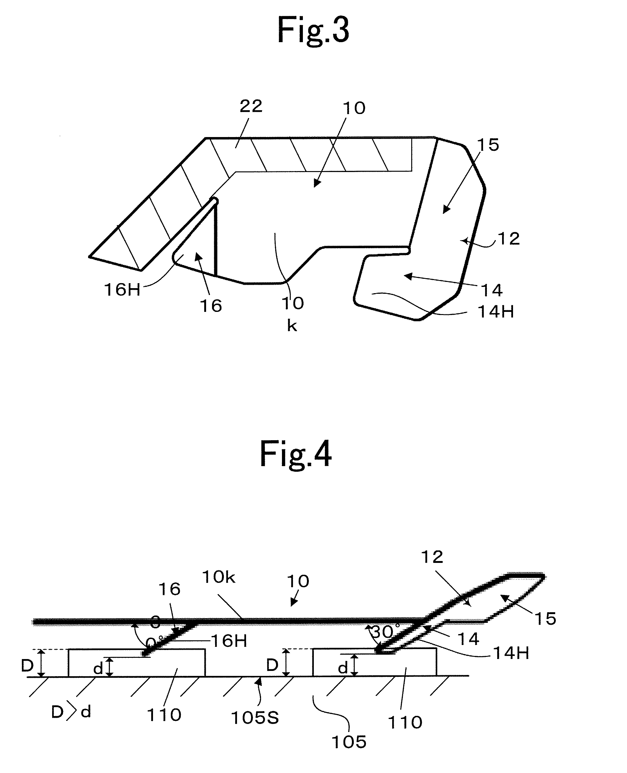
A pressing member having a body member with a first downwardly inclined plate and a second downwardly inclined plate is configured for mounting on a coin feeding apparatus to control the translation of coins on a rotary selector disk as they are released. The coins experience a downward force from the inclined plates to push them against the surface of the rotary disk to ensure that the coins remain within the predetermined translation path for the coins. A blocking plate can be extended upward from the body member adjacent the upstream downwardly extending plate, to prevent a rising of the coins to ensure the coins passes under the canopy of the pressing member across the translation path.

Description

BACKGROUND OF THE INVENTION[0001]1. Field of the Invention[0002]The present invention relates to a coin feeding apparatus for coins that are accommodated in a storage portion, separated by a rotation disk, and fed to a feed-out coin port, and more particularly to a coin feeding apparatus suitable for providing an accurate release of coins fed out along an outer periphery of the rotation disk by way of centrifugal force against a controlled resistance.[0003]2. Description of Related Art[0004]As one example of a conventional technique of a coin feeding apparatus, a rotation disk is provided inside a hopper and coins are scraped out one by one by a claw provided on the rotation disk and moved upward. The coins are received on a coin rail at an exit near a top portion to be guided to a coin mechanism from the exit along the rail, as shown in Japanese Laid-Open Patent Application No. 2000-298749.[0005]In such a conventional technique, a coin can inadvertently drop off the claw due to vib...

Claims


Application Information

Patent Timeline
Patent Type & Authority Applications(United States)
IPC IPC(8): G07D1/00
CPCG07D9/008G07D3/128
Inventor ENOMOTO, MINORU
Owner ASAHI SEIKO CO LTD
Why Eureka
Try Eureka