Control device for vehicular power transmitting device

a technology of transmission device and control device, which is applied in the direction of electric propulsion mounting, dynamo-electric gear control, gear control, etc., can solve the problem that the electric motor cannot obtain adequate regeneration amount, and achieve the effect of reducing electrical load, increasing regeneration amount and/or charging amount, and reducing electric power consumption

Inactive Publication Date: 2009-01-29
TOYOTA JIDOSHA KK
View PDF2 Cites 9 Cited by
  • Summary
  • Abstract
  • Description
  • Claims
  • Application Information

AI Technical Summary

Benefits of technology

[0020]With the control device for the vehicular power transmitting device according to the third aspect of the present invention, the case in which the electric motor is operated with priority to perform the charging and / or the electric power generation refers to the phase in which the vehicle remains in the electrical drive mode. Thus, increasing the regeneration amount can minimize electric power consumption caused during the electrical drive mode.
[0021]With the control device for the vehicular power transmitting device according to a fourth aspect of the present invention, the case in which the electric motor is operated with priority to perform the charging and / or the electric power generation refers to the phase in which the vehicle has the increasing electrical load. Thus, increasing the regeneration amount and / or the charging amount can reduce electrical load (electric power consumption).
[0022]With the control device for the vehicular power transmitting device according to the fifth aspect of the present invention, the shifting point effectuated with the control device is the downshift point of the shifting portion. This allows the downshift to be effectuated in the shifting portion during the regeneration mode, causing an increase in rotational speed of the shifting portion at the input side thereof. This can increase in the rotation speed of the electric motor, with an accompanying increase in the regeneration amount.
[0023]With the control device for the vehicular power transmitting device according to the sixth aspect of the present invention, the vehicular power transmitting device further comprises the electrically controlled differential portion disposed between the drive-force source and the drive wheels. The electrically controlled differential portion is operative to control the operating state of the controlling electric motor for thereby controlling the differential state between the rotation speed of the input shaft and the rotation speed of the output shaft which is connected to the shifting portion at the input side thereof. Therefore, initiating the downshift in the shifting portion can increase in the rotation speeds of the input side of the shifting portion and the output shaft of the electrically controlled differential portion. This causes the rotation speed of the electric motor to increase, with an accompanying increase in the regeneration amount. In addition, controlling the controlling electric motor can properly control the rotation speeds of the various rotary elements of the electrically controlled differential portion.
[0024]With the control device for the vehicular power transmitting device according to the seventh aspect of the present invention, the shifting portion of the vehicular power transmitting device includes the step-variable automatic shifting portion. Therefore, if the vehicle state comes to the downshift point, then the automatic shifting is initiated with an accompanying increase in speed ratio. With such an increase in speed ratio, the rotation speed of the input side of the shifting portion increases, thereby causing the electric motor to have an increased regeneration amount.
[0025]With the control device for the vehicular power transmitting device according to the eighth aspect of the present invention, the electrically controlled differential portion of the vehicular power transmitting device is rendered operative to act as the continuously variable shifting mechanism. This enables drive torque to be smoothly varied. In addition, the electrically controlled differential portion has functions not only to operate as the electrically controlled continuously variable transmission to obtain a continuously variable speed ratio, but also to operate as the step-variable transmission with the speed ratio varied step-by-step. Thus, the vehicular power transmitting device can achieve the various gear positions step-by-step, enabling drive torque to be rapidly obtained.

Problems solved by technology

In addition, due to limited torque of the electric motor, the electric motor can hardly obtain adequate regeneration amount (electric power generation amount).

Method used


Image

  • Control device for vehicular power transmitting device
  • Control device for vehicular power transmitting device
  • Control device for vehicular power transmitting device

Examples


embodiment

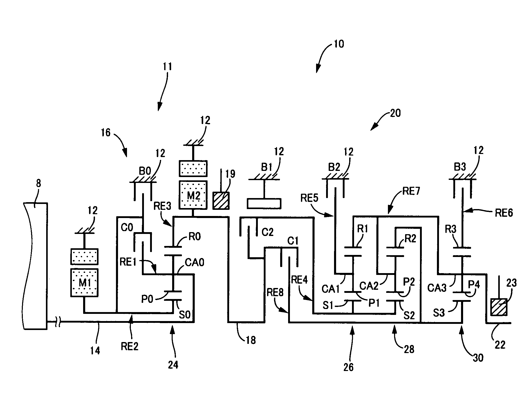
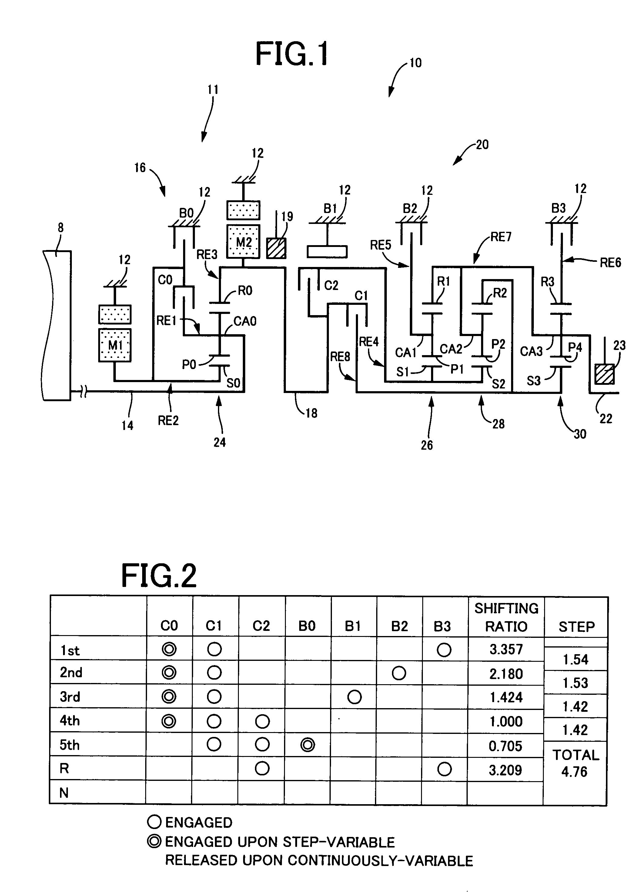
[0038]FIG. 1 is a skeleton view illustrating a shifting mechanism 10, forming part of a drive apparatus for a hybrid vehicle, to which a control device of one embodiment according to the present invention is applied. As shown in FIG. 1, the shifting mechanism 10 includes an input shaft 14 serving as an input rotary member, a differential portion 11 directly connected to the input shaft 14 or indirectly connected thereto through a pulsation absorbing damper (vibration damping device) not shown, an automatic shifting portion 20 connected via a power transmitting member (transmission shaft) 18 in series through a power transmitting path between the differential mechanism 11 and drive wheels 38 (see FIG. 6) to serve as a step-variable type transmission, and an output shaft 22 connected to the automatic shifting portion 20 as an output rotary member. All of them are disposed in a transmission casing 12 (hereinafter briefly referred to as a “casing 12”) serving as a non-rotary member conn...


PUM


Abstract

This invention relates to a control device for a vehicular power transmitting device. The control device has shifting-point altering means 108 operative such that when a second electric motor M2 is operated with priority to obtain a charging efficiency and/or electric power generating efficiency, a shifting point for a vehicle to run under a decelerating state (during a coast running state) is altered to a point on a higher vehicle speed than that at which a shifting point for a running-performance-conscious state is set. Therefore, when the second electric motor M2 is operated with priority for generating electric power, a downshift is initiated at a high vehicle speed than that at which the downshift is initiated at a shifting point for a running-performance-conscious state. This increases a rotation speed NM2 of the second electric motor M2, resulting in an increase in regeneration amount (electric power generation amount) of the second electric motor M2.

Description

TECHNICAL FIELD[0001]The present invention relates to a control device for a vehicular power transmitting device having a shifting portion forming part of a power transmitting path between the drive-force source and drive wheels and an electric motor connected to the power transmitting path. More particularly, it relates to a technology of performing a regeneration control for a coast running mode to achieve an increased regeneration amount and drivability in compatibility.BACKGROUND ART[0002]There has been known a control device for a vehicular power transmitting device including a shifting portion forming part of a power transmitting path between the drive-force source and drive wheels, and an electric motor connected to an input of the shifting portion. For instance, Patent Publication 1 (Japanese Patent Application Publication No. 2006-2913) discloses such a vehicular power transmitting device of a hybrid type. With the control device disclosed in Patent Publication 1, a differe...

Claims


Application Information

Patent Timeline
Patent Type & Authority Applications(United States)
IPC IPC(8): B60W10/12B60K6/445B60K6/547B60L15/20B60L50/16B60W10/08B60W10/10B60W10/18B60W10/26B60W20/00F16H59/74F16H61/10F16H61/68F16H61/684F16H61/686F16H63/50
CPCB60K1/02Y10T477/606B60K6/445B60K6/48B60K6/547B60L2240/421B60L2240/441B60L2240/443B60L2240/486B60W10/08B60W10/115B60W20/00B60W2510/0638B60W2510/0657B60W2510/1015B60W2510/104B60W2520/10B60W2710/081F16H3/728F16H61/0213F16H2037/0873Y02T10/6221Y02T10/642Y02T10/7258Y02T10/6239Y10S903/945Y10T477/33B60K6/365Y02T10/62Y02T10/64Y02T10/72B60K2006/4833B60W20/13B60W10/26
Inventor MATSUBARA, TOORUSHIBATA, HIROYUKIKUMAZAKI, KENTATABATA, ATSUSHI
Owner TOYOTA JIDOSHA KK
Why Eureka
Try Eureka