Automatic machine system and wireless communication method thereof

Active Publication Date: 2009-01-29
YASKAWA DENKI KK
View PDF16 Cites 30 Cited by
  • Summary
  • Abstract
  • Description
  • Claims
  • Application Information

AI Technical Summary

Benefits of technology

[0038]According to the first to fourth aspects of the invention, the field intensity of the communication data of the wireless communication can be monitored by the teaching unit and the controller respectively, and an alarm is given when the field intensity is equal to or smaller than the first threshold which is preset, and stops the driving operation of the mechanism unit when the field intensity is equal to or smaller than the second threshold which is preset. Therefore, there is an advantage that the portable teaching operation unit can be prevented from being operated by the operator at the outside of the operating range and a safety of an automatic machine can be enhanced.
[0039]According to the fifth aspect of the invention, the first or second field intensity monitoring portion gives the alarm when the field intensity is equal to or smaller than the preset first threshold continuously at the preset number of times. Consequently, there is an advantage that it is possible to prevent a false discrimination from being caused by only one accidental reduction in the field intensity.
[0040]According to the sixth and seventh aspects of the invention, the preset thresholds of the field intensity and the preset number of times are set to be the parameters in the first or second field intensity monitoring portion. Consequently, it is possible to produce an advantage that the operator can carry out a regulation depe

Problems solved by technology

For this reason, there is a problem in that a great burden is imposed on

Method used


Image

  • Automatic machine system and wireless communication method thereof
  • Automatic machine system and wireless communication method thereof
  • Automatic machine system and wireless communication method thereof

Examples


Example

First Example

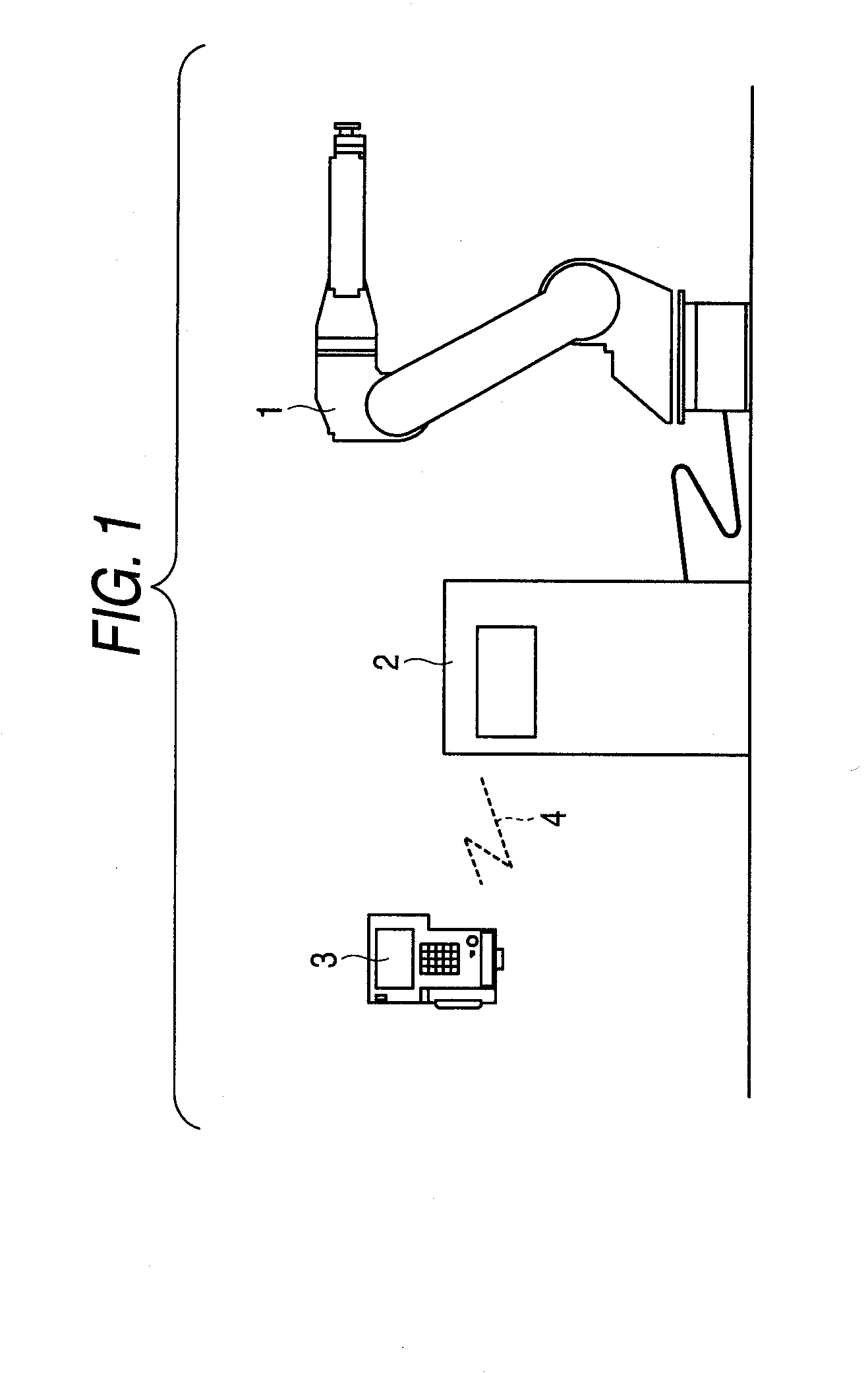
[0092]FIG. 1 is a view showing a structure of an automatic machine (which is assumed to be a robot) system according to a first example of the invention. In the drawing, 1 denotes a robot, 2 denotes a controller for controlling an operation of the robot 1, 3 denotes a portable teaching operation unit, and 4 denotes a wireless communication for transmitting information about an operation button or an emergency stop between the controller 2 and the portable teaching operation unit 3 (the reference numeral 4 is typically shown).

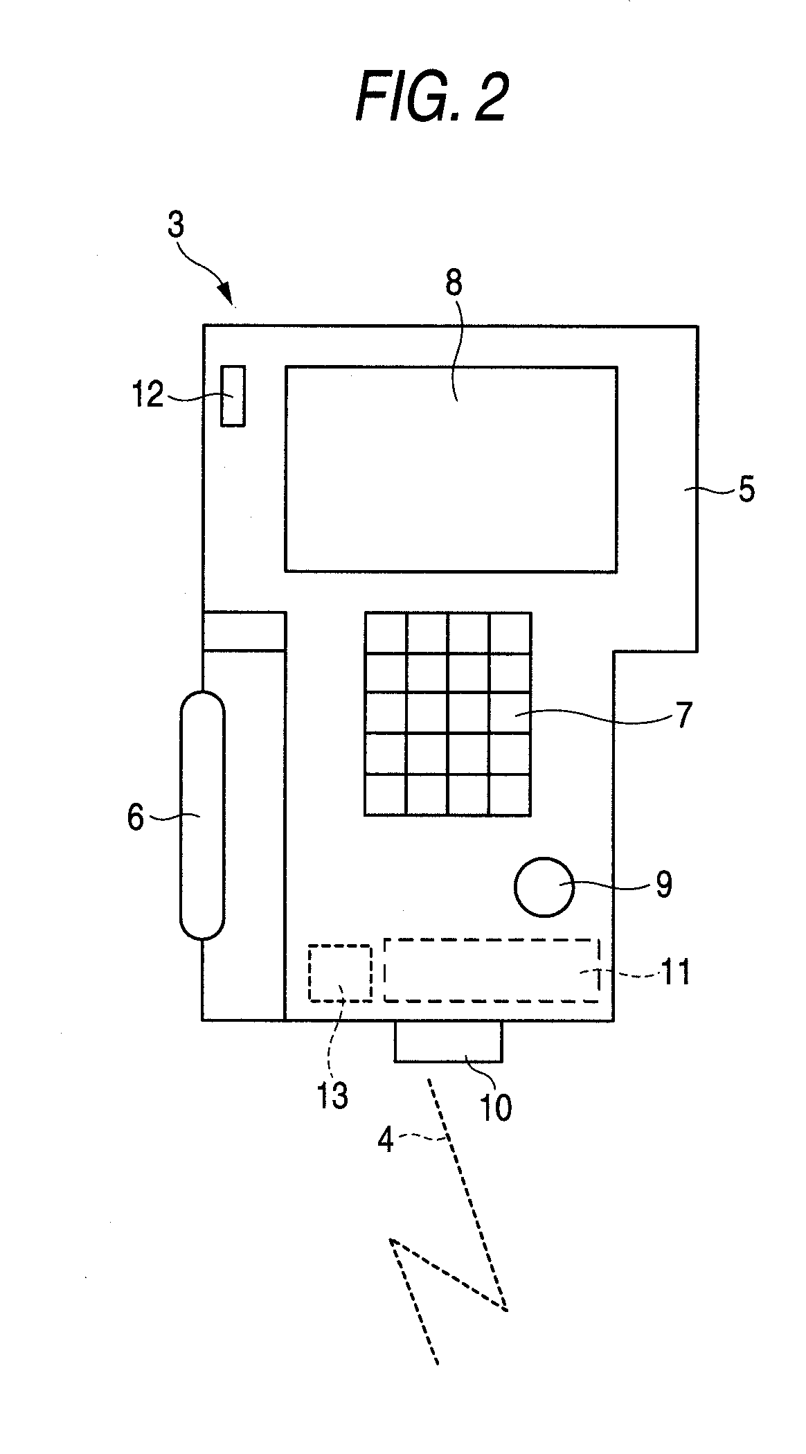
[0093]FIG. 2 is a view showing the details of the portable teaching operation unit 3. In the drawing, 5 denotes a housing taking an almost T shape and 6 denotes a hand portion to be gripped by an operator. An operation surface of the housing 5 is provided with a keyboard (or a key sheet) 7 to be operated by the operator in a teaching work, an LCD display 8 for displaying various information such as teaching data and a robot position, and an emergenc...

Example

Second Example

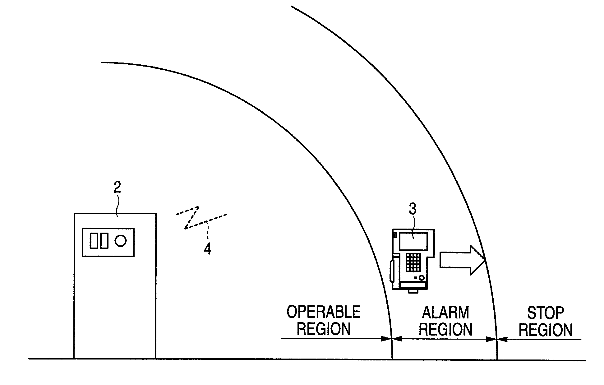
[0104]In the case in which the operator disregards the alarm displayed on the LCD display 8 of the portable teaching operation unit 3, and furthermore, gets out of the operable region of the wireless communication 4, the robot 1 is not under control of the operator. For this reason, it is necessary to block the supply of the power to the drive motors 23 of the robot 1 by an emergency stopping operation in order to prevent a danger. A second example according to the invention takes the fact into consideration.

[0105]As shown in FIG. 4, when the operator further moves in such a direction as to separate from the controller 2, the field intensities monitored by the first field intensity monitoring portion 13 and the second field intensity monitoring portion 26 are reduced to be equal to or smaller than a second threshold B which is preset (B is a real number which is greater than zero, and A>B is set). In this case, an intention of the operator is not transmitted to the con...

Example

Third Example

[0110]In order to enhance the operability of the operator, it is necessary to prevent a false discrimination when monitoring the field intensity of the wireless communication 4. A third example according to the invention deals with the problem.

[0111]In the case in which the field intensities monitored by the first field intensity monitoring portion 13 and the second field intensity monitoring portion 26 are reduced continuously with the passage of time, it is possible to prevent a false discrimination due to only one accidental reduction in the intensity and to reliably identify that a distance between the portable teaching operation unit 3 and the controller 2 is increased by deciding a change every preset time with respect to the field intensity. More specifically, in the case in which a state in which the field intensity of the wireless communication 4 is equal to or smaller than the preset threshold A is continuously brought at a preset number of times C (C is a nat...


PUM


Abstract

In an automatic machine system comprising a mechanism unit (1) including at least one driving mechanism, a controller (2) for controlling a driving operation of the mechanism unit (1), and a teaching unit (3) for operating the mechanism unit (1),
the teaching unit (3) includes a teaching unit communicating portion for carrying out a wireless communication with the controller (2) and a first field intensity monitoring portion (13) for monitoring a field intensity of communication data in the teaching unit communicating portion, and
the controller (2) includes a controller communicating portion for carrying out a wireless communication with the teaching unit (3), a second field intensity monitoring portion (26) for monitoring a field intensity of communication data in the controller communicating portion, and a driving portion for driving the mechanism unit (1) based on an operation signal sent from the teaching unit (3) in the controller communicating portion.

Description

TECHNICAL FIELD[0001]The present invention relates to an automatic machine system for connecting a controller and a teaching unit in an automatic machine through a wireless communication, and a wireless communication method thereof.BACKGROUND ART[0002]A system for controlling an automatic machine, a motor and an industrial robot has a control unit for controlling operations of the automatic machine, the motor and the robot, and furthermore, has a portable teaching operation unit carried by an operator in a teaching work (which is also referred to as a pendant). For an information transmission of the teaching unit and the control unit, conventionally, a twisted pair wire or an optical fiber has been used as a signal transmission path and a composite cable including a power supply wire to the teaching operation unit (which will be hereinafter referred to as a cable) has been utilized.[0003]As an example, FIG. 7 is a view showing a structure of a conventional robot system described in ...

Claims


Application Information

Patent Timeline
IPC IPC(8): G06F19/00B25J19/00B25J19/06G05B19/18G05B19/42
CPCB25J19/06F16P3/14G08C2201/20G05B2219/49137G08C17/02G05B19/4061G05D1/02
Inventor NAGATA, HIDEOTANAKA, MICHIHARU
Owner YASKAWA DENKI KK
Why Eureka
Try Eureka