System and method of determining the area of vulnerability for estimation of voltage sags and computer-readable medium having embodied thereon computer program for the method

a vulnerability and estimation method technology, applied in the field of power systems, can solve problems such as voltage drop, voltage in the system, load sensitive to the change in voltage, misoperation or stop operation of loads, etc., and achieve the effect of rapid calculation of the vulnerability area

Inactive Publication Date: 2009-01-29
KOREA UNIV IND & ACAD COLLABORATION FOUNDATION
View PDF6 Cites 22 Cited by
  • Summary
  • Abstract
  • Description
  • Claims
  • Application Information

AI Technical Summary

Benefits of technology

[0013]The present invention provides a system and method which can rapidly perfo

Problems solved by technology

Voltage sags are one of the most important power-quality (PQ) problems and known as voltage dips during a short time.
Voltage sags are mainly caused by faults in a power system.
When a fault occurs, a voltage in the system decreases, and loads sensitive to the change in the voltage may misoperate or stop operating.
As the loads sensitive to the change in the voltage have been increasingly used, financial losses due to vol

Method used


Image

  • System and method of determining the area of vulnerability for estimation of voltage sags and computer-readable medium having embodied thereon computer program for the method
  • System and method of determining the area of vulnerability for estimation of voltage sags and computer-readable medium having embodied thereon computer program for the method
  • System and method of determining the area of vulnerability for estimation of voltage sags and computer-readable medium having embodied thereon computer program for the method

Examples


Embodiment Construction

[0030]Hereinafter, exemplary embodiments of the present invention will be described in detail with reference to the attached drawings.

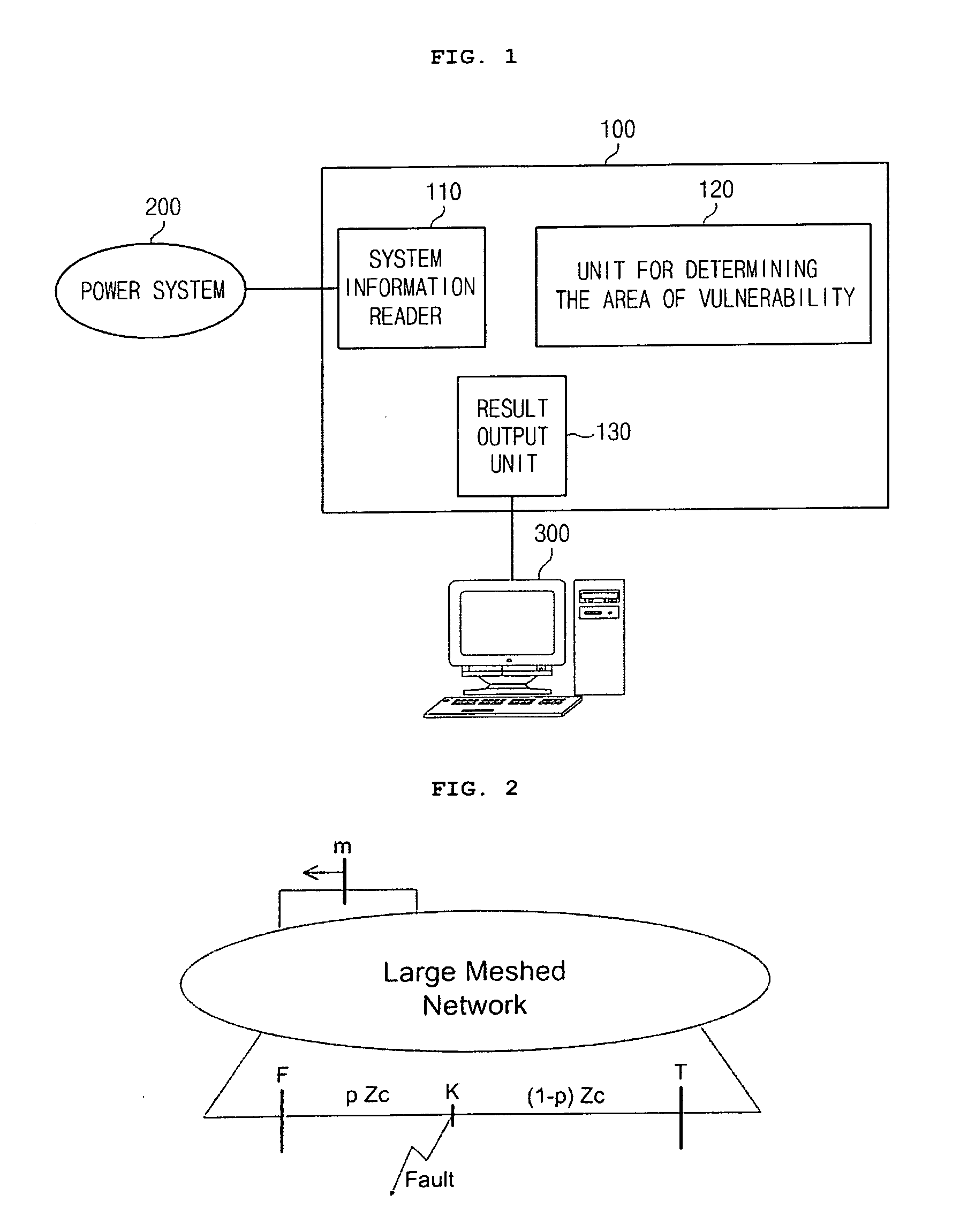
[0031]FIG. 1 is a schematic block diagram illustrating a system for determining the area of vulnerability for estimation of voltage sags according to the present invention. Referring to FIG. 1, the system 100 for determining the area of vulnerability is connected to a power system 200 and a user terminal 300 and includes a system information reader 110, a unit 120 for determining the area of vulnerability, and a result output unit 130.

[0032]The system information reader 110 reads information on the power system 200. The unit 120 for determining the area of vulnerability determines information on the area of vulnerability for a predetermined line by using the system information. The result output unit 130 outputs a result of the determination the area of vulnerability performed by the unit 120 for determining the area of vulnerability to the user termi...


PUM


Abstract

Provided is a system for determining the area of vulnerability for estimation of voltage sages including: a system information reader reading information on a power system; a unit for determining the area of vulnerability calculating a voltages at a target bus corresponding to ends of a fault line by using the system information and a first residual voltage equation that is a voltage relationship between points in the fault line in the power system where a fault is simulated and the target bus where a voltage change due to the fault occurs, calculating a voltage at the target bus corresponding to a point between the ends when the voltages at the target bus corresponding to the ends are not higher than a predetermined voltage threshold, deriving a second residual voltage equation that is an approximate quadratic interpolation equation for the first residual voltage equation by using the voltages at the target bus corresponding to the ends and the point between the ends of the fault line, calculating the voltage of the target bus corresponding to the point of the fault line by using the second residual voltage equation, and determining the point of the fault line corresponding to a voltage of the target bus equal to or lower than the predetermined voltage threshold as the area of vulnerability; and a result output unit outputting results of the determination of the area of vulnerability.

Description

BACKGROUND OF THE INVENTION[0001]1. Field of the Invention[0002]The present invention relates to a power system, and more particularly, to a system and method for improving power-quality.[0003]2. Description of the Related Art[0004]Voltage sags are one of the most important power-quality (PQ) problems and known as voltage dips during a short time. According to IEEE Standard 1159-1995, a voltage is the decrease in rms voltage between 0.1 and 0.9 p.u. at the power frequency for durations from 0.5 cycles to 1 min. Voltage sags are mainly caused by faults in a power system.[0005]When a fault occurs, a voltage in the system decreases, and loads sensitive to the change in the voltage may misoperate or stop operating. As the loads sensitive to the change in the voltage have been increasingly used, financial losses due to voltage sags increase.[0006]Voltage magnitude and duration are essential characteristics of a voltage sag. The voltage sag magnitude mainly depends on not only the fault l...

Claims


Application Information

Patent Timeline
IPC IPC(8): G01R31/40
CPCG01R19/2513H02H3/34H02J13/00
Inventor JANG, GIL-SOOPARK, CHANG-HYUN
Owner KOREA UNIV IND & ACAD COLLABORATION FOUNDATION
Why Eureka
Try Eureka