Air Conditioning System for Car

Active Publication Date: 2009-02-05
HANON SYST
View PDF9 Cites 27 Cited by
  • Summary
  • Abstract
  • Description
  • Claims
  • Application Information

AI Technical Summary

Benefits of technology

[0017]Accordingly, the present invention has been made to solve the above-mentioned problems occurring in the prior art, and it is an object of the present invention to provide an air conditioning system for a car, which can automatically remove a malodor generated due to condensate water remaining i

Problems solved by technology

However, since the air filter, in fact, is arranged in front of the evaporator which is the root of the malodor, the air filter can remove the malodor contained in the air introduced from the outside, but cannot directly remove a malodor generated from the evaporator itself.
So, if the air conditioner is continuously operated, the malodor generated from the evaporator is discharged to the inside of the car in itself when the air introduced from the outside by the blower unit passes through the evaporator, so that the driver or the passengers may feel severe unpleasantness.
Particularly, since the air filter is fixed at its installation place with no change of position and always exposed to the air blown from the blower unit, when a pre-determined period of time is passed, the odor composition is adsorbed and gathered into fine pores of active carbon and reaches saturation,

Method used


Image

  • Air Conditioning System for Car
  • Air Conditioning System for Car
  • Air Conditioning System for Car

Examples


Example

Embodiment 1

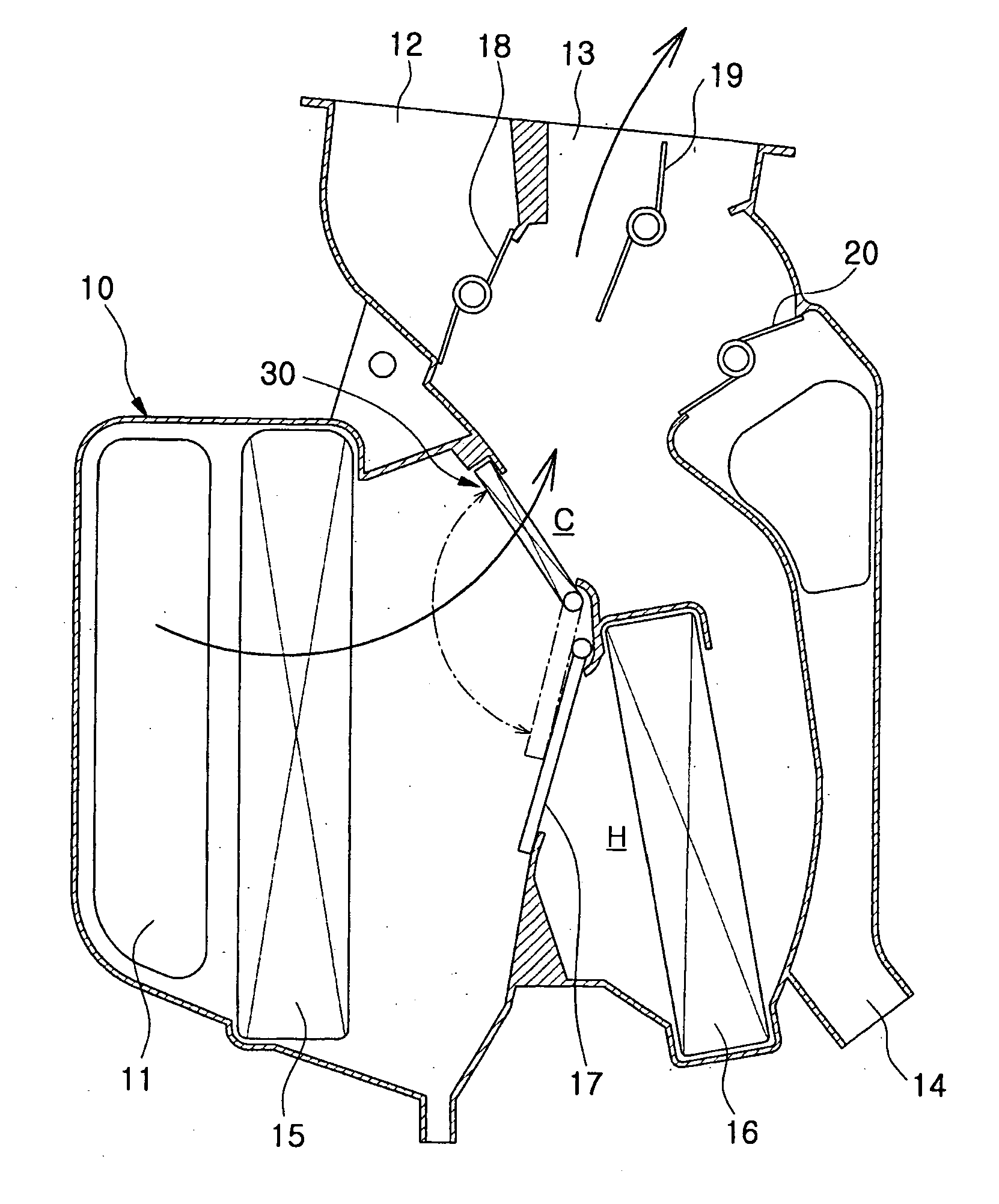
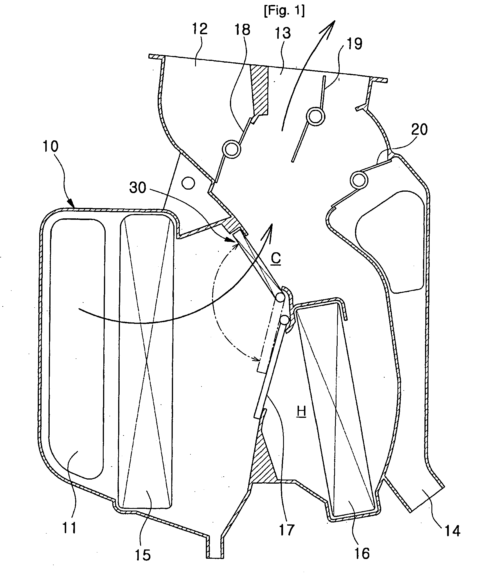
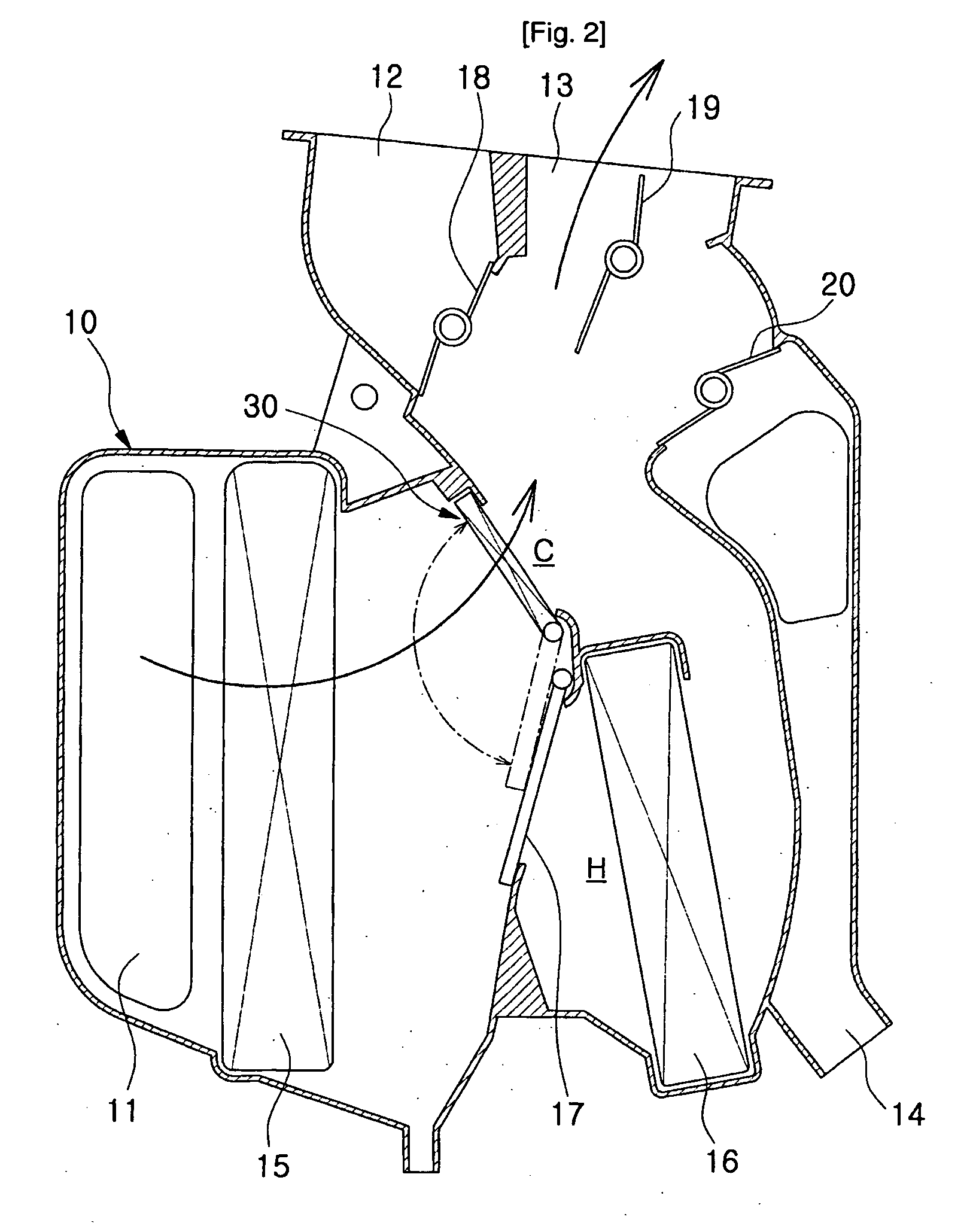
[0044]FIG. 2 is a sectional view of an air conditioning system for a car according to a first preferred embodiment of the present invention, showing a state of a filtering mode during the maximum cooling mode, FIG. 3 is a configurative view of a temperature door of FIG. 2, FIG. 4 is a configurative view of a shiftable deodorization filter of FIG. 2, and FIG. 5 is a sectional view of an air conditioning system for a car according to a first preferred embodiment of the present invention, showing a state of a non-filtering mode during the maximum cooling mode.

[0045]An air conditioning system for a car according to this embodiment is a semi-center mounting type air conditioning system having an evaporator and a heater core, which are integrated with each other in a case.

[0046]That is, as shown in FIG. 2, the air conditioning system for the car includes an air conditioning case 10 having an air inlet 11 formed at an entrance part of a side thereof and a plurality of air outle...

Example

Embodiment 2

[0072]FIG. 7 is a sectional view of an air conditioning system for a car according to a second preferred embodiment of the present invention, showing a state of a filtering mode during the maximum cooling mode, FIG. 8 is a configurative view of a shiftable deodorization filter of FIG. 7, and FIG. 9 is a sectional view of an air conditioning system for a car according to the second preferred embodiment of the present invention, showing a state of a non-filtering mode during the maximum cooling mode.

[0073]The second preferred embodiment has the same configuration and function as the first preferred embodiment excepting that the shiftable deodorization filter of the second embodiment has a slidable structure. So, same components have same reference numerals in drawings, and repeated description will be omitted.

[0074]As shown in FIG. 8, shiftable deodorization filter 40 according to the second preferred embodiment includes: a filter case 41 having an inner space and being cu...

Example

Embodiment 3

[0085]FIG. 11 is a sectional view of an air conditioning system for a car according to a third preferred embodiment of the present invention, showing a state of a filtering mode during the maximum cooling mode, and FIG. 12 is a configurative view of a temperature door of FIG. 11.

[0086]The third preferred embodiment has the same configuration and function as the first and second preferred embodiments excepting that the shiftable deodorization filter and the temperature door of the third embodiment have a structure that the shiftable deodorization filter and the temperature door described in the first and second embodiments are combined with each other. So, same components have same reference numerals in drawings, and repeated description will be omitted.

[0087]As shown in FIG. 11, the shiftable deodorization filter 30 according to this embodiment is mounted at a position different from that of the shiftable deodorization filter 30 of the first embodiment, but has the same ...


PUM

PropertyMeasurementUnit
Temperatureaaaaaaaaaa
Timeaaaaaaaaaa

Abstract

An air conditioning system, which can automatically remove a malodor generated due to condensate water remaining in an evaporator during a predetermined period of time after operation of an air conditioner or turning-off of the air conditioner and control a filtering mode time of a filter to filter an air. The air conditioning system characteristically comprises a shiftable deodorization filter (30 or 40) located on a flow channel of the cool air passageway and operationally moved to a filtering mode position so as to screen the flow channel of the cool air passageway during a predetermined period of time after an air conditioner is turned on or off, whereby the air passing through the cool air passageway C and a malodor contained in the air are filtered.

Description

TECHNICAL FIELD[0001]The present invention relates to an air conditioning system for a car, and more particularly, to an air conditioning system for a car, which can automatically remove a malodor generated due to condensate water remaining in an evaporator during a certain period of time after operation of an air conditioner or turning-off of the air conditioner and control a filtering mode time of a filter to filter an air, thereby keeping an agreeable environment inside the car and reducing a maintenance cost of the filter.BACKGROUND ART[0002]In general, an air conditioning system for a car selectively passes and heat-exchanges air introduced into the car by a blower unit toward an evaporator in which refrigerant flows or a heater core in which cooling water of an engine flows, and then, distributes cooled or heated air into the car in various directions through air outlets communicating with components mounted inside the car.[0003]Such air conditioning system includes an air fil...

Claims


Application Information

Patent Timeline
IPC IPC(8): B60H1/32B01D27/00
CPCB60H1/00064B60H2003/065B60H3/0085B60H1/00B60H1/32
Inventor KIM, JAE-HOJEE, YONG-JUNHAN, SEONG-SEOK
Owner HANON SYST
Why Eureka
Try Eureka