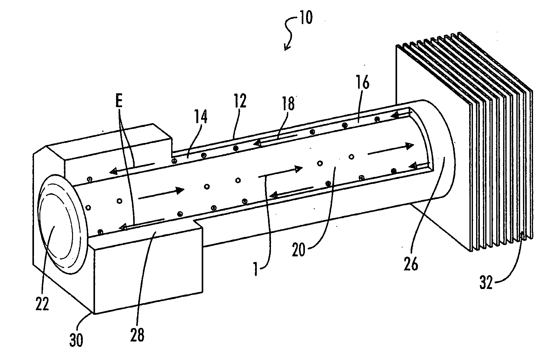
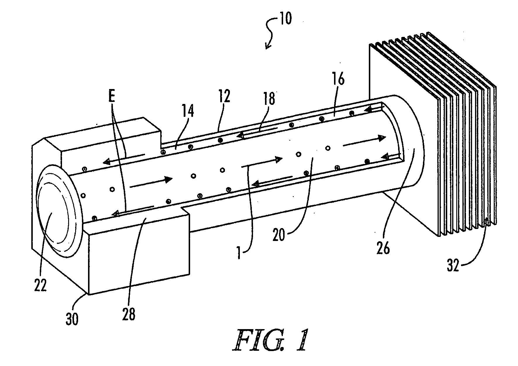
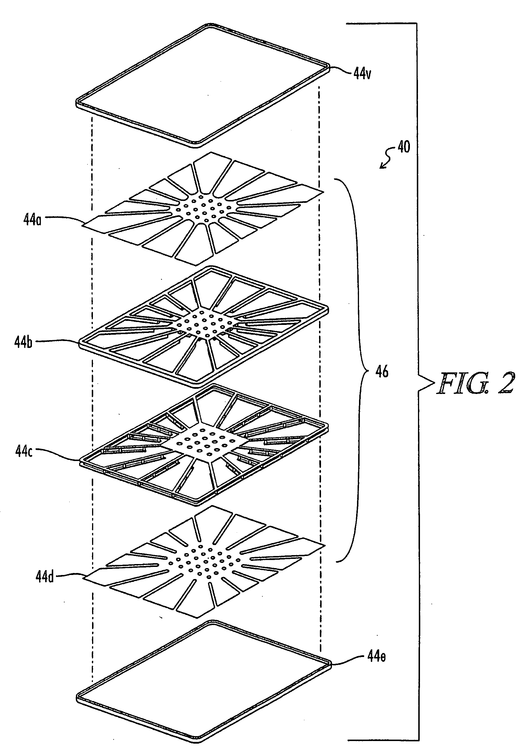
Flexible Graphite Thermal Management Devices

a graphite thermal management and flexible technology, applied in the direction of indirect heat exchangers, heat exchange apparatus, light and heating apparatus, etc., can solve the problems of unusability in some situations, unsatisfactory conventional heat pipe structure, extreme critical factors of weight and space, etc., to achieve satisfactory thermal conductivity, excellent weight, and acceptable rigidity

Inactive Publication Date: 2009-02-05
GRAFTECH INT HLDG INC
View PDF28 Cites 17 Cited by
  • Summary
  • Abstract
  • Description
  • Claims
  • Application Information

AI Technical Summary

Benefits of technology

[0011]Thermal management devices of the present invention have many advantages when compared to their conventional counterparts, some of which include excellent weight, acceptable rig

Problems solved by technology

However, there are applications for which the conventional heat pipe structure is not satisfactory.
Metal casings and metal wicks add weight, rigidity, and electrical conductivity to heat pipes, but that makes them unusable in some situations.
In such applications, we

Method used


Image

  • Flexible Graphite Thermal Management Devices
  • Flexible Graphite Thermal Management Devices
  • Flexible Graphite Thermal Management Devices

Examples


Embodiment Construction

[0018]Graphites may be characterized as laminated structures of carbon, that is, structures consisting of superposed layers or laminae of carbon atoms joined together by weak van der Waals forces. In considering the graphite structure, two axes or directions are usually noted, to with, the “c” axis or direction and the “a” axes or directions. For simplicity, the “c” axis or direction may be considered as the direction perpendicular to the carbon layers. The “a” axes or directions may be considered as the directions parallel to the carbon layers or the directions perpendicular to the “c” direction. The graphites suitable for manufacturing flexible graphite sheets possess a very high degree of orientation.

[0019]As noted above, the bonding forces holding the parallel layers of carbon atoms together are only weak van der Waals forces. Natural graphites can be treated so that the spacing between the superposed carbon layers or laminae can be appreciably opened up so as to provide a marke...


PUM

PropertyMeasurementUnit
Fractionaaaaaaaaaa
Poweraaaaaaaaaa
Densityaaaaaaaaaa

Abstract

The invention provides to thermal management devices constructed from flexible graphite. In one embodiment, the thermal management device includes a wick structure inside a shell. In certain preferred embodiments, the wick structure is composed of a mass of expanded graphite. In a another embodiment, the shell of the device includes flexible graphite and an optional wick structure. In certain preferred embodiments, the flexible graphite shell is fluid impermeable. The invention further includes methods of making the aforementioned thermal management devices.

Description

FIELD OF THE INVENTION[0001]The invention relates to thermal management devices, and more particularly, to such devices, which include flexible graphite and methods of making such devices.BACKGROUND OF THE INVENTION[0002]Thermal management devices, such as heat pipes, are devices which are known in the art of heat transfer. A heat pipe is essentially a closed system of heat transfer in which a small amount of liquid within a sealed and evacuated enclosure is cycled through an evaporation and condensation cycle. Heat entering the enclosure at one location on the casing evaporates liquid at that location, producing vapor, which moves to a cooler location on the casing where it is condensed. The movement of the vapor is motivated by a small vapor pressure differential between the evaporator and the condenser locations. The heat transfer is accomplished when the heat of vaporization, which produces the vapor, is essentially moved with the vapor to the condenser location where it is give...

Claims


Application Information

Patent Timeline
IPC IPC(8): F28F21/02F28D15/02F28D15/04C04B41/48
CPCC04B41/009C04B41/4857C04B2111/50F28D15/046F28F21/02C04B35/536F28D15/00F28D15/02F28F23/00
Inventor KRASSOWSKI, DANIEL W.CHEN, GRAY G.BURKETT, THOMAS W.FORD, BRIAN M.TZENG, JING-WENNORLEY, JULIANSMALC, MARTIN D.
Owner GRAFTECH INT HLDG INC
Why Eureka
Try Eureka