Display Rack Assembly for Wrenches with Different Handles

a technology of display racks and wrenches, which is applied in the direction of transportation and packaging, tray containers, rigid containers, etc., can solve the problems of not being able to simulate the operating conditions of wrenches, not being able to provide the simulation of wrenches, and potential customers, etc., to facilitate the description of invention

Inactive Publication Date: 2009-02-05
HU BOBBY
View PDF10 Cites 9 Cited by
  • Summary
  • Abstract
  • Description
  • Claims
  • Application Information

AI Technical Summary

Problems solved by technology

However, none of them allow try-on of wrenches under load.
Specifically, none of the currently existing display racks provide simulation of operating conditions of wrenches, particularly wrenches with twisted handles or wrenches with handles having tapered widths in each of two pairs of opposite faces thereof.
Potential customers are, thus, lost.

Method used


Image

  • Display Rack Assembly for Wrenches with Different Handles
  • Display Rack Assembly for Wrenches with Different Handles
  • Display Rack Assembly for Wrenches with Different Handles

Examples


Embodiment Construction

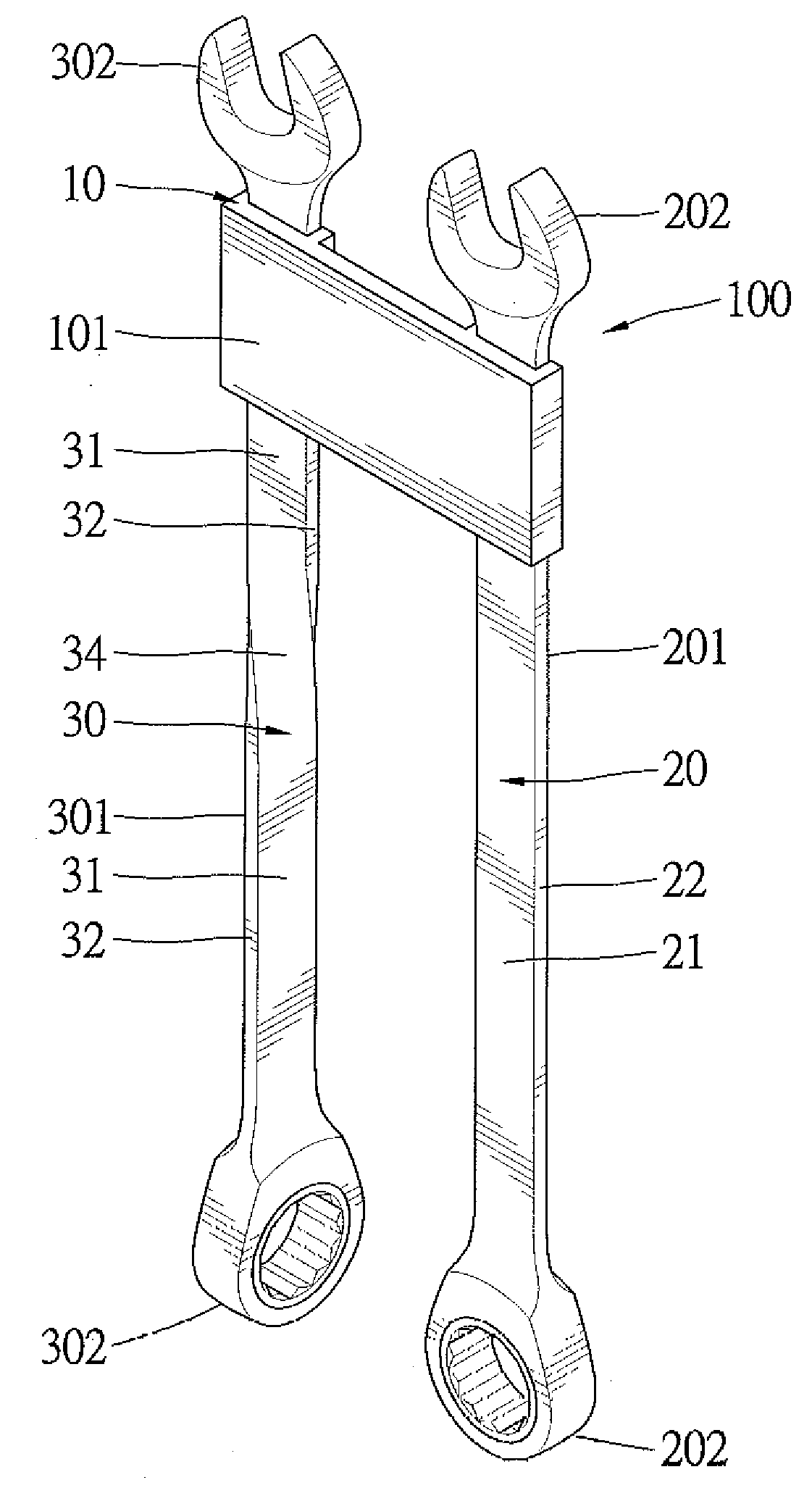
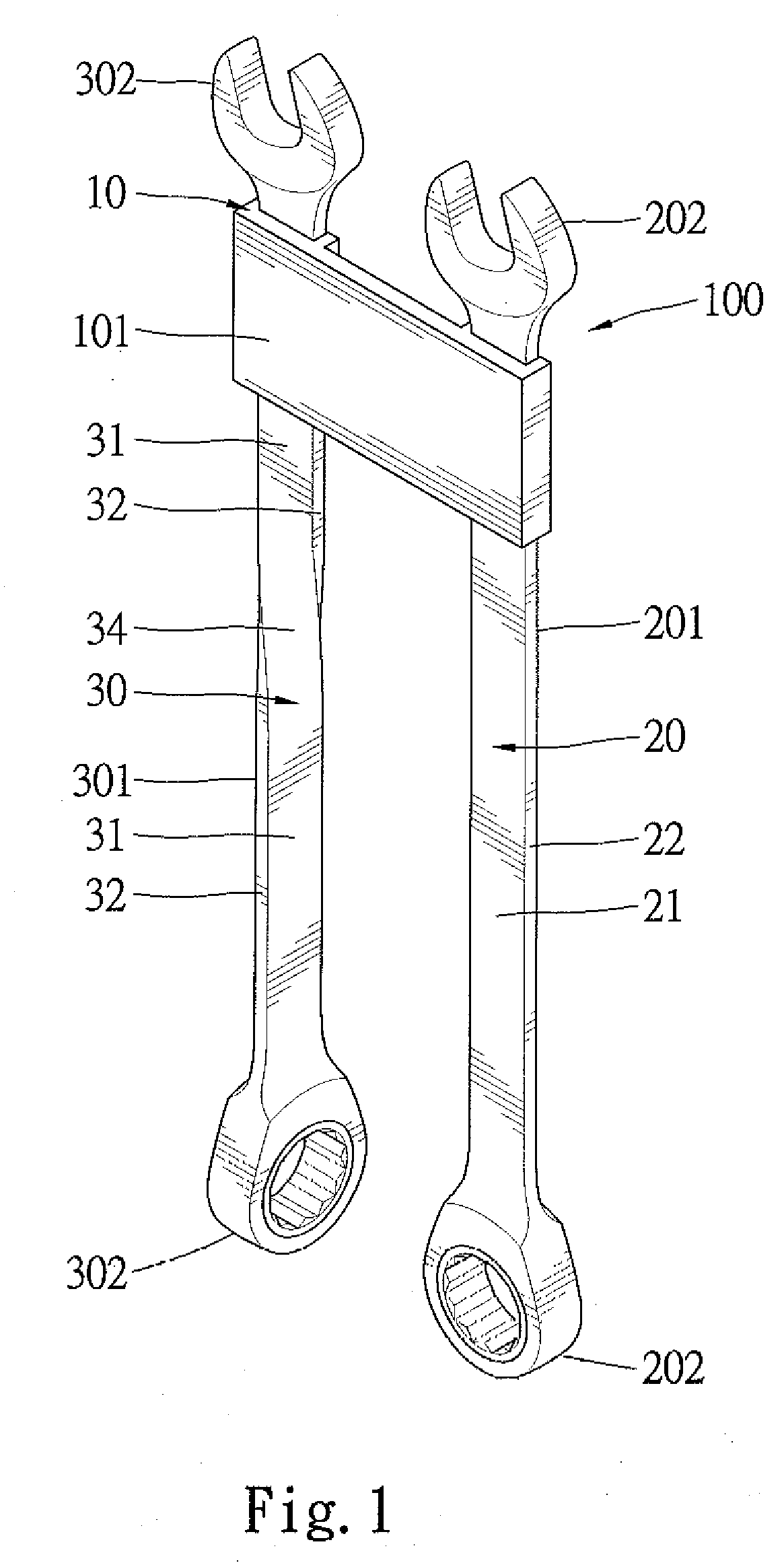
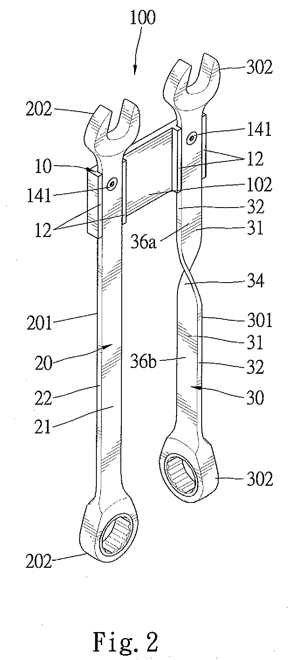
[0020]A display rack assembly of a first embodiment according to the preferred teachings of the present invention is shown in FIGS. 1-5 of the drawings and generally designated 100. The display rack assembly 100 includes a rack 10 having first and second coupling sections 11. According to the preferred form shown, the rack 10 includes rectangular cross sections and has a front face 101 and a rear face 102. Each of the first and second coupling sections 11 includes two parallel, spaced positioning walls 12 on the rear face 102 thereof. A positioning groove 18 is defined between the positioning walls 12 of each of the first and second coupling sections 11 and includes a bottom wall 16 having a screw hole 13.

[0021]A first wrench 20 includes a first handle 201 in the most preferred form of a flat handle having first and second ends 202 for driving fasteners. The first and second ends 202 of the first wrench 20 may be of any desired forms including but not limited to open ends and box en...


PUM


Abstract

A display rack assembly includes a rack having two coupling sections for releasably and fixedly coupling with a first wrench with a first handle and a second wrench with a second handle. The second handle includes a handle section having two opposite wider faces perpendicular to two opposite wider faces of the first handle. The handle section further includes two opposite narrower faces perpendicular to two opposite narrower faces of the first handle. A customer may hold one of the narrower faces of the first handle and one of the wider faces of the handle section of the second handle and apply a rotational force to try the wrenches.

Description

BACKGROUND OF THE INVENTION[0001]The present invention relates to a display rack assembly and, more particularly, to a display rack assembly allowing try-on of wrenches with different handles.[0002]To provide a display effect for attracting potential buyers, wrenches are often packaged in hanger boards hung on hooks in a market. The hanger boards are arranged according to the types of the wrenches to obtain the required display effect without try-on function. Taiwan Patent Application No. 94117498 discloses a display rack to which a wrench is rotatably mounted to provide a try-on function. Display racks of other arrangements have also been proposed allowing users to try wrenches. However, none of them allow try-on of wrenches under load. Specifically, none of the currently existing display racks provide simulation of operating conditions of wrenches, particularly wrenches with twisted handles or wrenches with handles having tapered widths in each of two pairs of opposite faces there...

Claims


Application Information

Patent Timeline
Patent Type & Authority Applications(United States)
IPC IPC(8): A47F7/00B65D85/00
CPCA47F7/0028
Inventor HU, BOBBY
Owner HU BOBBY
Why Eureka
Try Eureka