Swing type bilateral non-sine drive device of continuous casting crystallizer

A continuous casting crystallizer and driving device technology, applied in the field of continuous casting, can solve the problems of low operating precision, poor operating mode, and difficult control, etc., achieve superior wear resistance, reduce operating and maintenance costs, and avoid environmental pollution Effect

Inactive Publication Date: 2016-02-03
YANSHAN UNIV
View PDF9 Cites 8 Cited by
  • Summary
  • Abstract
  • Description
  • Claims
  • Application Information

AI Technical Summary

Problems solved by technology

However, in the current electric drive device, the operation mode of the servo motor with frequent variable speed and reverse rotatio...

Method used


Image

  • Swing type bilateral non-sine drive device of continuous casting crystallizer
  • Swing type bilateral non-sine drive device of continuous casting crystallizer
  • Swing type bilateral non-sine drive device of continuous casting crystallizer

Examples


Embodiment 1

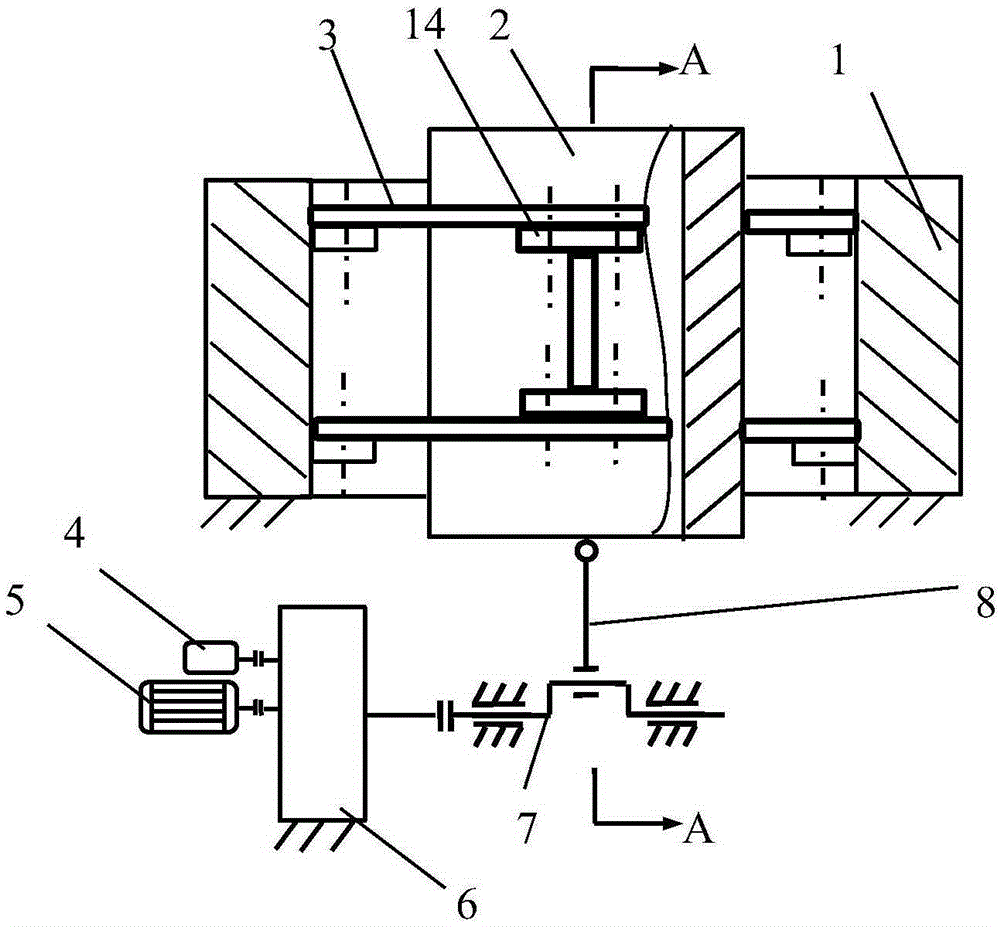
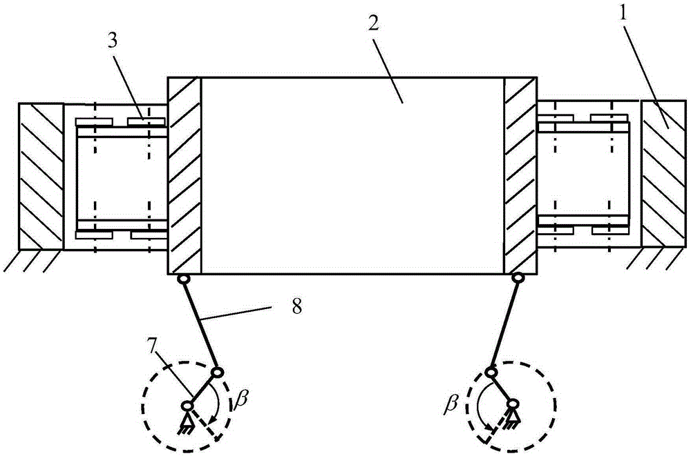
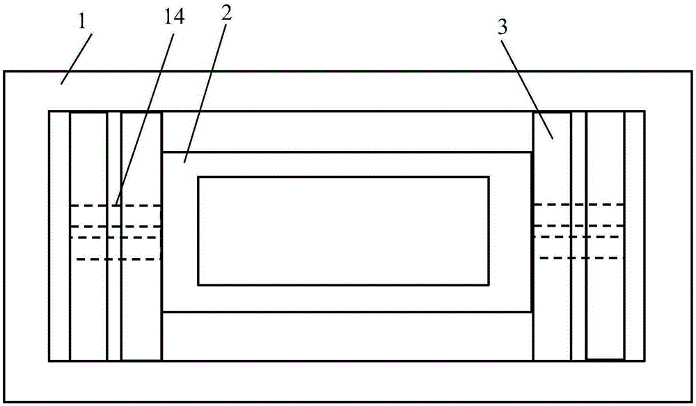
[0033] exist figure 1 , figure 2 and image 3 In the schematic diagram of the continuous casting mold swing type double-sided non-sinusoidal driving device shown, the crystallizer vibrating table is composed of a fixed frame 1, a vibrating frame 2 and the connecting pieces between them, and a vibrating frame is arranged in the fixed frame , each side of the two narrow sides of the vibrating frame is provided with a total of four guide leaf springs 3, the two ends of the guide leaf springs are respectively connected to the fixed frame through connectors, and the middle part of the guide leaf springs is connected to the I-shaped support beam 14 through the connectors. The fixed end of the I-shaped support beam is vertically connected with the middle part of the narrow surface of the vibrating frame. The crystallizer vibrating table of this scheme is used in straight arc continuous casting machines. The vibrating frame reciprocates along a straight line, and the centerlines of...

Embodiment 2

[0048] The structure of this embodiment is basically the same as that of Example 1, except that the active component connection mode of the differential gear train transmission mechanism 6 is changed, such as Figure 11 As shown, the constant speed motor 5 is connected with the small sun gear 12 through a coupling, the servo motor 4 is connected with the driving gear 9 through a coupling, and the driving wheel 9 drives the planet carrier 11 to rotate through the fixed gear on the planet carrier 11 . After the angular velocity of the constant speed motor 5 and the servo motor 4 is synthesized by the differential gear train 6 , the motion is transmitted to the shock shaft 7 through the big sun gear 10 .

[0049] The given crystallizer vibration parameters are the same as the first group of vibration parameters in Embodiment 1: amplitude h=4mm, vibration frequency f=180min -1 , the waveform eccentricity slope α=0.2, then setting the speed of the servo motor 4 can achieve the vibr...


PUM


Abstract

The invention discloses a swing type bilateral non-sine drive device of a continuous casting crystallizer. The swing type bilateral non-sine drive device mainly comprises two identical waveform generators and a crystallizer vibration table. A vibration frame is arranged in a fixed frame. At least two guide plate springs are arranged on each side of two narrow faces of the vibration frame. The two ends of each plate spring are connected with the fixed frame, and the center lines of all the plate springs are parallel and perpendicular to the vibration direction of the crystallizer. A normal-speed motor and a servo motor of each waveform generator are meshed with two driving components of a differential gear train transmission mechanism respectively, and driven components of the differential gear train transmission mechanisms are connected with shock wave shafts. The shock wave shafts of the two waveform generators are symmetrically arranged below the two narrow faces of the vibration frame; one or two eccentric wheels are arranged on each shock wave shaft; the eccentric wheels are connected with the vibration frame through connecting rods; and the two ends of the connecting rods are hinged to the eccentric wheels and the vibration frame respectively. The swing type bilateral non-sine drive device is easy to control, high in running precision and good in impact resistance, prime mover one-way rotation is achieved, and all the amplitude, the waveform and the frequency can be adjusted online.

Description

technical field [0001] The invention belongs to the field of continuous casting, in particular to a non-sinusoidal vibration device of a crystallizer. Background technique [0002] Continuous steel casting is the core link of steel production at present. During the process of pouring molten steel into the crystallizer, the mold must vibrate according to certain rules to ensure the lubrication conditions between the casting slab and the mold, thereby preventing the mold from forming a gap between the mold and the new slab shell. A steel breakout accident caused by bonding between them. With the in-depth understanding of various complex physical mechanisms between the slab and the mold, non-sinusoidal vibration is recognized as the optimal waveform for high-efficiency continuous casting. Therefore, the development of advanced non-sinusoidal Driving equipment has always been a hot topic in engineering circles at home and abroad. [0003] For billets, round billets and slab mo...

Claims


Application Information

Patent Timeline
IPC IPC(8): B22D11/053
Inventor 刘大伟
Owner YANSHAN UNIV
Why Eureka
Try Eureka