AC generator for vehicles

a generator and vehicle technology, applied in the direction of electrical equipment, dynamo-electric machines, supports/enclosements/casings, etc., can solve the problems of increasing length, physical inability to fix with screws, and affecting the service performance of ac generators, so as to achieve the effect of further reducing the deformation of the l-shaped suppor

Inactive Publication Date: 2009-02-05
DENSO CORP
View PDF5 Cites 29 Cited by
  • Summary
  • Abstract
  • Description
  • Claims
  • Application Information

AI Technical Summary

Benefits of technology

[0014]The present invention has been made in light of the circumstances provided above, and has as its object to provide an AC generator for vehicles, which is able to reduce bending stress generated in fixedly screwing the leads of the stator windings to the rectifier.

Problems solved by technology

In this case, if the side wall interferes with the screwing position of the rectifier, the fixation with a screw will be physically impossible.
As mentioned above, in the case where the side wall of the rear housing is axially extended toward the rear cover, welding or soldering for fixation of the leads may impair the service performance of the AC generator because of the presence of the side wall of the rear housing.
However, the change in the screwing position of each lead of the stator windings may cause, in turn, another problem of increasing the length of the lead.
If cooling air is directly blown to the sealed portion of each of the rectifying elements, an electrically conductive liquid containing a snow melting agent, for example, is very likely to be directly in contact with the sealed portion, which will create undesirable conditions as far as the environmental resistance is concerned.
However, there is a long distance between the fixedly screwing portion provided at the end of each L-shaped support and the base portion of the L-shaped support on the side of the rear housing.
Thus, problematically excessive bending stress of assemblage has been caused at the base portion of each lead of the stator windings, as well as the caulked portion between the lead and the metal terminal attached to the end of the lead.
However, these approaches may involve high manufacturing cost and high component cost.
Thus, if emphasis is put on reducing the costs, these approaches are difficult to be employed.

Method used


Image

  • AC generator for vehicles
  • AC generator for vehicles
  • AC generator for vehicles

Examples


Embodiment Construction

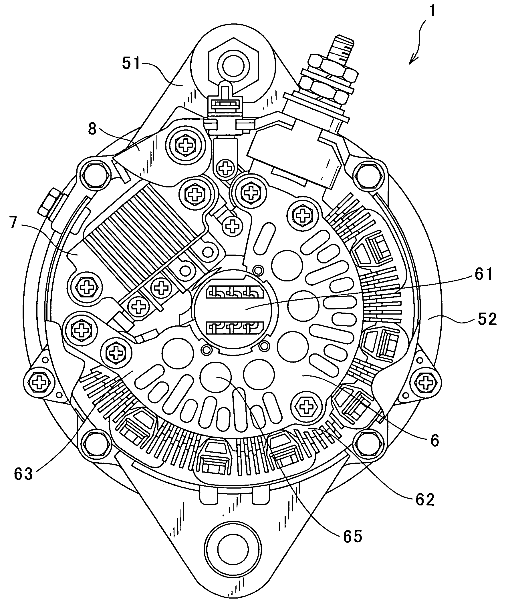
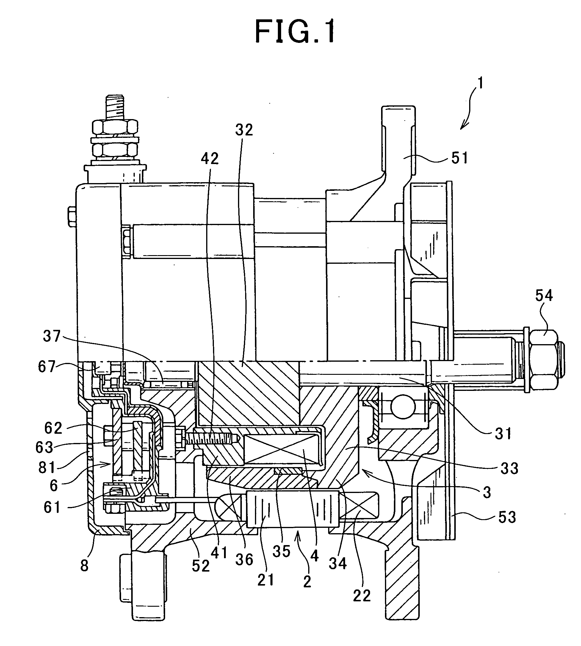
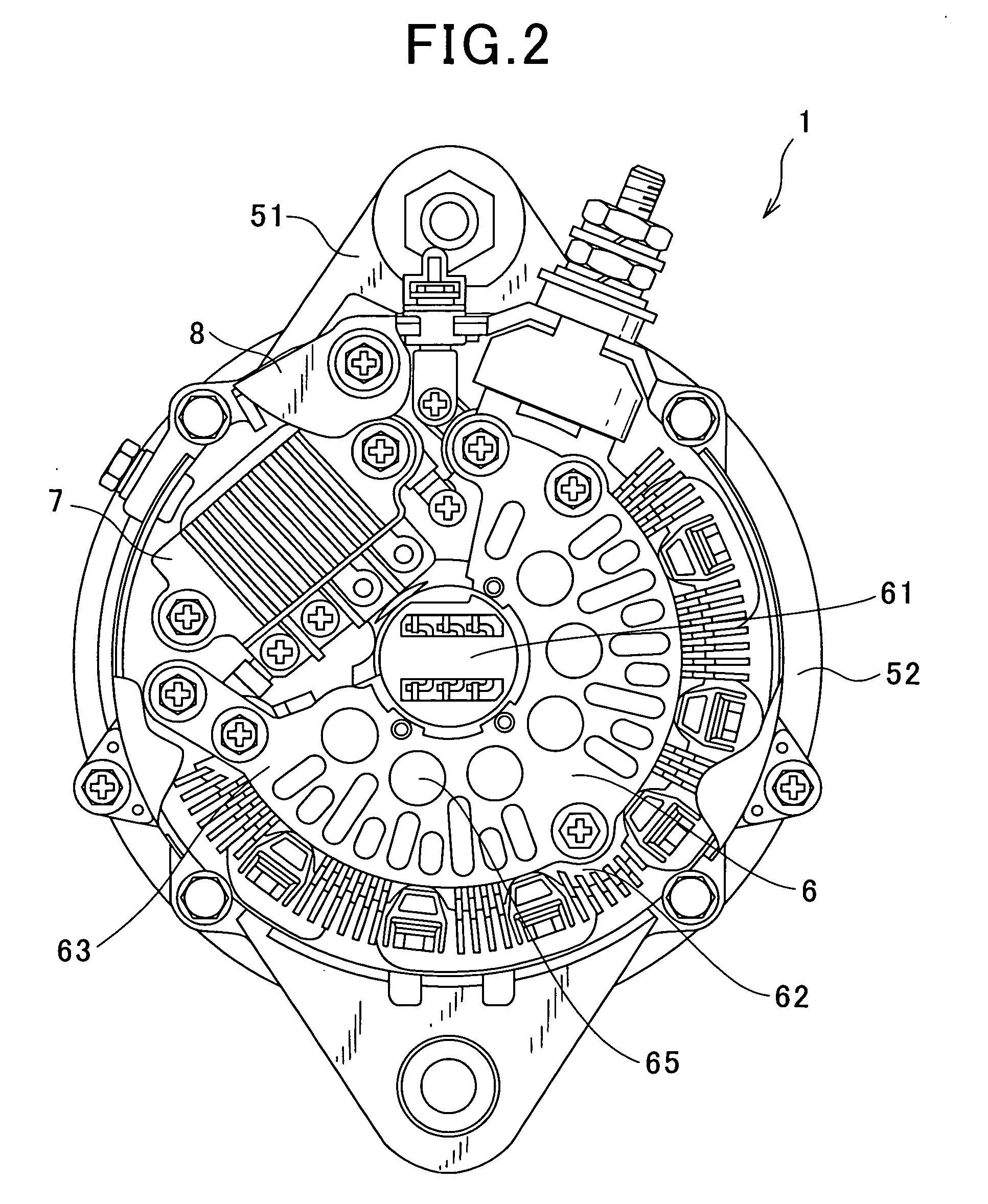
[0037]With reference to the accompanying drawings, hereinafter will be described, in detail, a brushless AC (alternating current) generator for vehicles according to an embodiment of the present invention. FIG. 1 is a partial cross-sectional side view illustrating a general configuration of the brushless AC generator for vehicles, according to the embodiment. FIG. 2 is a rear view illustrating a general configuration of the brushless AC generator for vehicles according to the embodiment.

[0038]As shown in FIGS. 1 and 2, a brushless AC generator 1 for vehicles (hereinafter just referred to “brushless AC generator 1”) includes a stator 2, a rotor 3, field windings 4, a front housing 51, a rear housing 52, a rectifier 6, a regulator 7 and a rear cover 8.

[0039]The stator 2 serves as an armature and is provided with a stator core 21 having turns of stator windings 22. The rotor 3 serves as a field magnet and is disposed on the side of the inner periphery of the stator 2, being opposed the...


PUM


Abstract

According to an AC generator for vehicles of the present invention, a terminal mount includes an L-shaped support having a radial extension, in which a metal terminal is contained and which radially extends about a rotary shaft of a rotor, and an axial extension, which extends from an end of the radial extension toward a rear cover along the rotary shaft, and at least one first guide molded integral with the L-shaped support. A radiating fin includes a second guide having a shape corresponding to a shape of the first guide. One of the first guide and the second guide is inserted into the other of the first guide and the second guide.

Description

CROSS REFERENCE TO RELATED APPLICATION[0001]This application is based on and claims the benefit of priority from earlier Japanese Patent Application No. 2007-202435 filed Aug. 3, 2007, the description of which is incorporated herein by reference.BACKGROUND OF THE INVENTION[0002]1. Technical Field of the Invention[0003]The present invention relates to an AC generator (i.e., alternator) for vehicles, which is mounted, for example, in motor trucks, construction machines and agricultural machines.[0004]2. Related Art[0005]In recent years, manufacturers of passenger automobiles and motor trucks have made their continual efforts to improve the engines in order to comply with the emission regulations. This improvement thus tends to increase the ambient temperature of the components mounted on an engine. On the other hand, there is a yearly increasing demand for devices that ensure safety in travel, as well as increasing demand for additional power supplies and enhancement in in-vehicle ame...

Claims


Application Information

Patent Timeline
Patent Type & Authority Applications(United States)
IPC IPC(8): H02K11/00H02K5/18
CPCH02K5/20H02K11/046H02K9/06H02K5/225H02K5/207H02K11/05
Inventor HAMADA, HIROSHI
Owner DENSO CORP
Why Eureka
Try Eureka