

Rotational Angle Detection Device
a detection device and rotational angle technology, applied in the direction of galvano-magnetic devices, magnetic sensor geometrical arrangements, instruments, etc., can solve the problems of complex processing circuitry, and the patent document 3 does not disclose the relationship in detail for the rotational angle of rotating magnets
- Summary
- Abstract
- Description
- Claims
- Application Information
AI Technical Summary
Benefits of technology
Problems solved by technology
Method used
Image

Examples
first embodiment
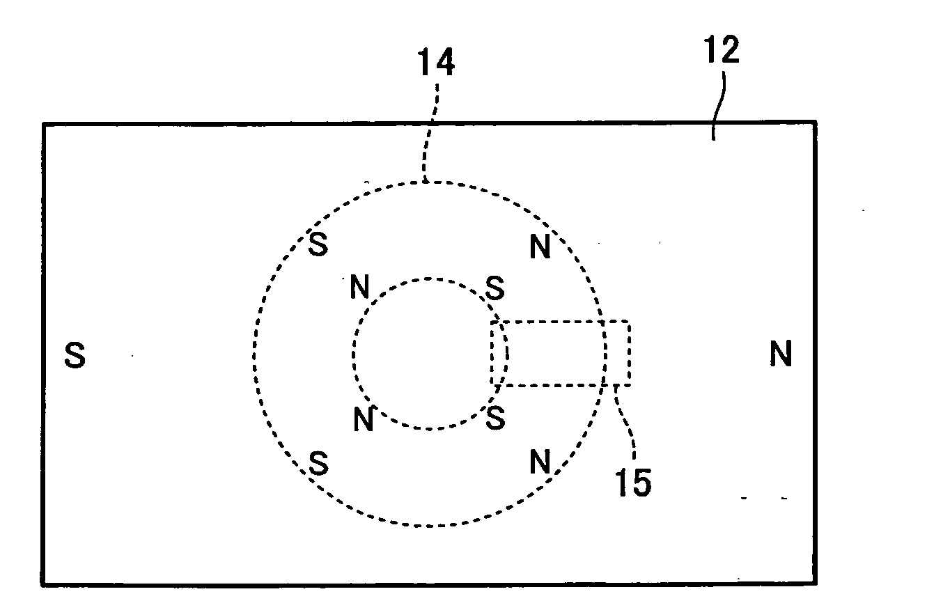
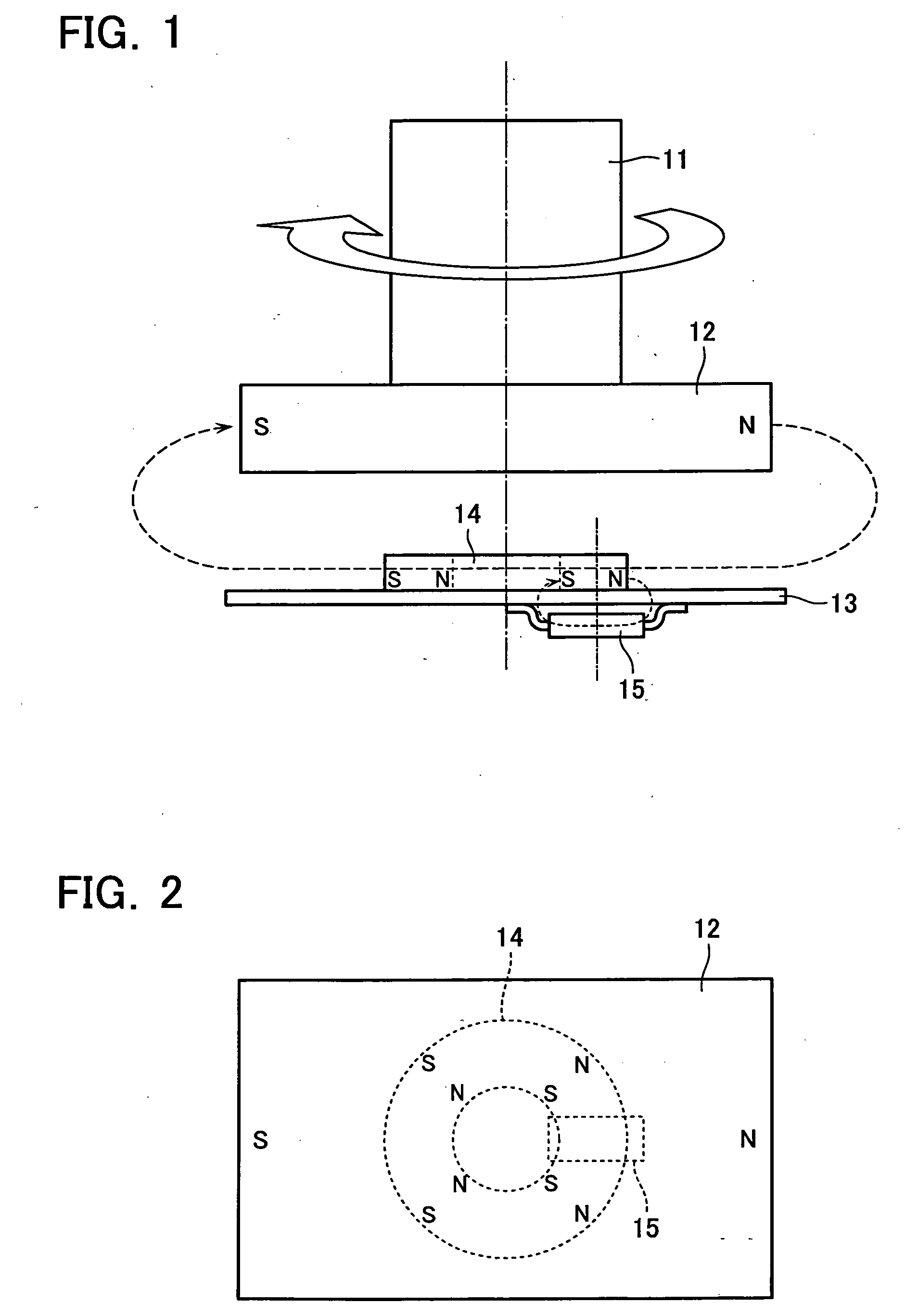
[0019]FIG. 1 is a side view illustrating a configuration of a rotational angle detection device according to a first embodiment of the present invention; and FIG. 2 is a plan view of the same device. The rotational angle detection device comprises: a rotating magnet 12, which is mounted on one end of a rotating shaft 11 as a detection object; a four-pole auxiliary magnet 14, which is mounted on a substrate 13 opposed to the rotating magnet 12 without contact; and a magnetic sensor 15, which is mounted on the opposite side of the substrate 13.
[0020]The detection object is the rotating shaft 11 of a motor or the like. In this first embodiment, shaft ends of the rotating shaft 11 can be used as a detection object. The rotating magnet 12, which has a shape of rectangular parallelepiped, is a two-pole permanent magnet with its poles being provided at both ends in its longitudinal direction. The four-pole auxiliary magnet 14 is a ring-shaped magnet that is coaxially positioned with respec...
second embodiment
[0040]FIG. 7 is a side view illustrating a configuration of a rotational angle detection device according to a second embodiment of the present invention. This embodiment is suitable for a case where such shaft ends may not be available because a steering angle of an automobile is detected from a shaft rotational angle of an assisting electric motor.
[0041]A rotating shaft 31 as the detection object is equipped with a ring-shaped rotating magnet 32. A ring-shaped four-pole auxiliary magnet 34 is mounted on a substrate 33 that is positioned on the same surface as the rotating surface of the rotating magnet 32. In addition, a magnetic sensor 35 is mounted on the rear surface of the substrate 33. The magnetic sensor 35, which is similar to that in FIG. 10, is mounted on a displaced position with respect to the center of the four-pole auxiliary magnet 34 so that it would be positioned in a homogenous magnetic field generated by the four-pole auxiliary magnet 34.
[0042]In addition, in this...
PUM
 Abstract
Description
Claims
Application Information