Lane recognition image processing apparatus

a technology of image processing and lane recognition, which is applied in the field of lane recognition image processing apparatus, can solve the problems of reducing the reliability of the recognition result of a distant portion which is needed to precisely grasp the shape of the road, and the presence of objects other than the lane marking, so as to improve the recognition performance of the lane marking and reduce the possibility of misdetection

a technology of image processing and lane recognition, which is applied in the field of lane recognition image processing apparatus, can solve the problems of reducing the reliability of the recognition result of a distant portion which is needed to precisely grasp the shape of the road, and the presence of objects other than the lane marking, so as to improve the recognition performance of the lane marking and reduce the possibility of misdetection

US20060015252A1Active Publication Date: 2006-01-19MITSUBISHI ELECTRIC CORP

Image

  • Lane recognition image processing apparatus
  • Lane recognition image processing apparatus
  • Lane recognition image processing apparatus

Examples


embodiment 1

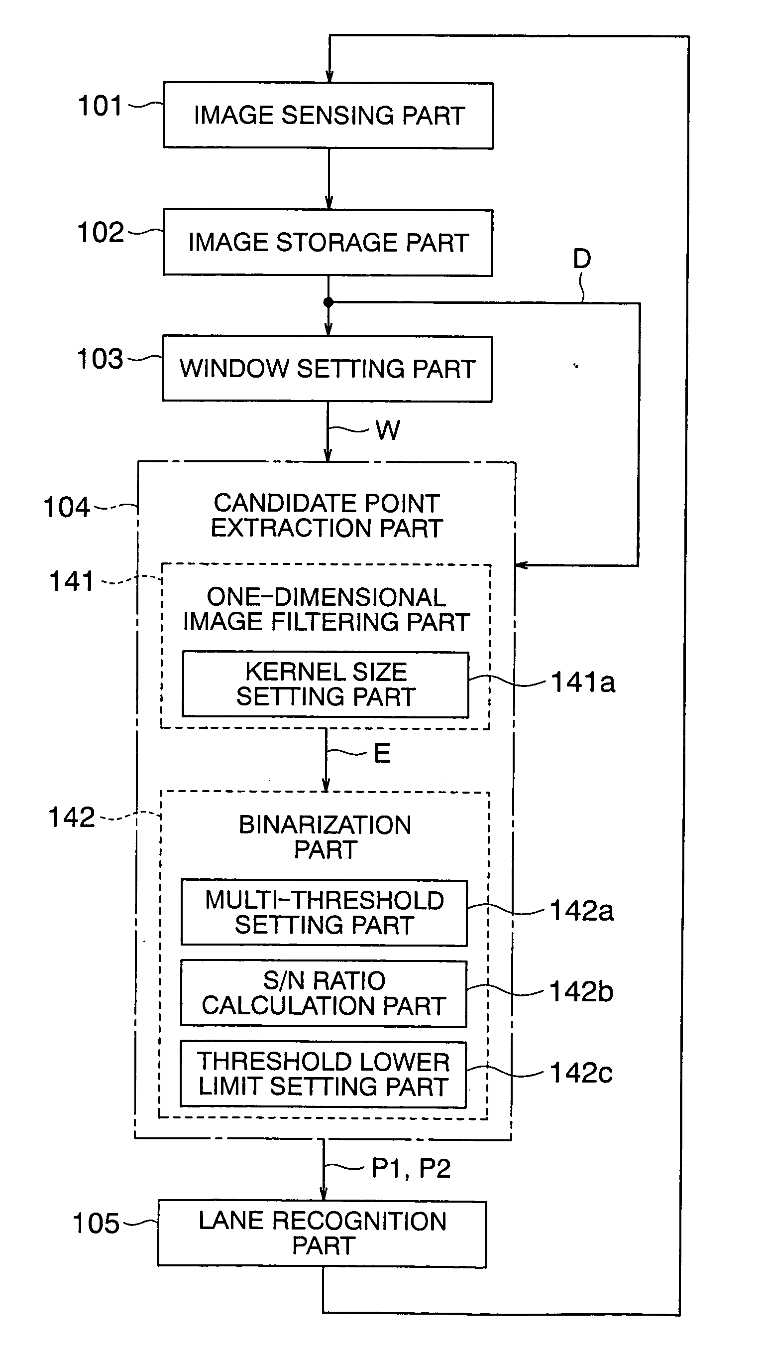
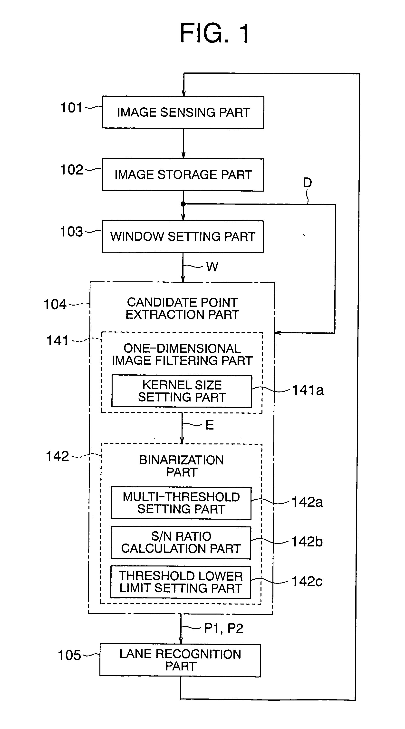
[0040]FIG. 1 is a block diagram that shows a lane recognition image processing apparatus according to a first embodiment of the present invention, wherein respective components thereof are illustrated so as to correspond to processing procedures. FIG. 2 is an external view that illustrates a vehicle 2 on which a lane recognition image processing apparatus according to the first embodiment of the present invention is installed.

[0041] In FIG. 2, a camera 1, which constitutes an image sensing part, is installed on a front upper portion of the vehicle 2, and takes a forward view of the vehicle 2.

[0042] In FIG. 1, the lane recognition image processing apparatus includes an image sensing part 101 having the camera 1 and installed on the vehicle 2 see FIG. 2) for recognizing a lane of a road based on the picked-up or sensed images of lane markings on a road surface, an image storage part 102 for temporarily storing the images obtained by the image sensing part 101, a window setting part ...

embodiment 2

[0124] Although in the above-mentioned first embodiment, only the model equation reference part is used in the setting of a window, a candidate point reference part 131b and a vanishing point reference part 131c can be added to or incorporated in the reference position setting part 131 in a window setting part 103A, and a vanishing point learning part 106 can also be provided for optimally setting the window W for each search line Vn, as shown in FIG. 15.

[0125]FIG. 15 is a block diagram showing a lane recognition image processing apparatus according to a second embodiment of the present invention in a manner to correspond to processing procedures, wherein the same or corresponding parts or elements as those in the above-mentioned first embodiment (see FIG. 1) are identified by the same symbols while omitting a detailed description thereof.

[0126] In FIG. 15, a major difference from the above-mentioned first embodiment (FIG. 1) is that the reference position setting part 131 in the ...


PUM


Abstract

A lane recognition image processing apparatus can improve lane marking recognition performance by preventing false detection by addition of a condition without changing the basic principle of an one-dimensional image filter. A search area is set for each lane marking with respect to images stored in a image storage part through a window. A candidate point extraction part extracts candidate points of each lane marking from the search area thus set. A lane marking mathematical model equation is derived by approximating sets of extracted candidate points by a mathematical model equation. The candidate point extraction part includes a kernel size setting part, a filtering part that outputs, as a filtering result, the smaller of differences between the gray value of a pixel of interest and those of pixels forwardly and rearwardly apart a kernel size from the pixel of interest in a scanning direction, respectively, and a binarization part that binarizes the filtering result.

Description

BACKGROUND OF THE INVENTION [0001] 1. Field of the Invention [0002] The present invention relates to a lane recognition image processing apparatus which is installed on a vehicle for recognizing a lane of a road based on the sensed or picked-up image of lane markings on the road on which the vehicle is travelling, and which is applied to an advanced vehicle control system such as a lane departure warning system (LDWS) intended for use with preventive safety of the vehicle such as an automobile, a lane keeping system (LKS) serving the purpose of reducing a cognitive load on drivers, etc. More particularly, the invention relates to a technique capable of improving reliability in the result of the recognition by providing vehicle lateral or transverse position information in the lane. [0003] 2. Description of the Related Art [0004] As a conventional lane recognition image processing apparatus, there has been known one using an image filter (for example, see a first patent document: Jap...

Claims


Application Information

Patent Timeline
19 Jan 2006
Publication
US20060015252A1
IPC
G01S1/00; G06G7/78
CPC
G01S5/16; G06K9/00798; G01S17/936; G01S11/12; G01S17/931; G06V20/588
Inventors
YAMAMOTO, TAKAYUKI; FUJII, YOSHIYUKI