
Imaging apparatus, imaging method, storage medium, and integrated circuit

Active Publication Date: 2009-02-05
PANASONIC CORP
View PDF4 Cites 26 Cited by
  • Summary
  • Abstract
  • Description
  • Claims
  • Application Information

AI Technical Summary

Benefits of technology

[0049]This imaging method is used in the imaging apparatus including the illumination unit that illuminates a subject with illumination light and the imaging unit that captures a plurality of images each under a different condition of the illumination unit. The imaging method has the same advantageous effects as the imaging apparatus of the first aspect of the present invention.
[0050]A fourteenth aspect of the present invention provides a program used in an imaging apparatus including an illumination unit for illuminating a subject with illumination light and an imaging unit for capturing a plurality of images each under a different condition of the illumination unit. The program enables a computer to function as an illumination light element obtaining unit, a reflectance estimation unit, and a distance information estimation unit. The illumination light element obtaining unit obtains an image formed with an element of the illumination light by eliminating a light element other than the illumination light element from the plurality of images captured by the imaging unit. The reflectance estimation unit eliminates illumination variations from one of the plurality of images captured by the imaging unit or from the image formed with the illumination light element, and estimates a reflectance of the subject corresponding to a pixel. The distance information estimation unit estimates a distance to the subject corresponding to the pixel based on the image formed with the illumination light element and the reflectance of the subject.
[0051]This program is used in the imaging apparatus including the illumination unit that illuminates a subject with illumination light and the imaging unit that captures a plurality of images each under a different condition of the illumination unit. The program has the same advantageous effects as the imaging apparatus of the first aspect of the present invention.
[0052]A fifteenth aspect of the present invention provides a computer readable storage medium storing a program used in an imaging apparatus including an illumination unit for illuminating a subject with illumination light and an imaging unit for capturing a plurality of images each under a different condition of the illumination unit. The program enables a computer to function as an illumination light element obtaining unit, a reflectance estimation unit, and a distance information estimation unit. The illumination light element obtaining unit obtains an image formed with an element of the illumination light by eliminating a light element other than the illumination light element from the plurality of images captured by the imaging unit. The reflectance estimation unit eliminates illumination variations from one of the plurality of images captured by the imaging unit or from the image formed with the illumination light element, and estimates a reflectance of the subject corresponding to a pixel. The distance information estimation unit estimates a distance to the subject corresponding to the pixel based on the image formed with the illumination light element and the reflectance of the subject.
[0053]The computer readable storage medium is used in the imaging apparatus including the illumination unit that illuminates a subject with illumination light and the imaging unit that captures a plurality of images each under a different condition of the illumination unit. The computer readable storage medium has the same advantageous effects as the imaging apparatus of the first aspect of the present invention.
[0054]An sixteenth aspect of the present invention provides an integrated circuit including an illumination unit, an imaging unit, an illumination light element obtaining unit, a reflectance estimation unit, and a distance information estimation unit. The illumination unit illuminates a subject with illumination light. The imaging unit captures a plurality of images each under a different condition of the illumination unit. The illumination light element obtaining unit obtains an image formed with an element of the illumination light by eliminating a light element other than the illumination light element from the plurality of images captured by the imaging unit. The reflectance estimation unit eliminates illumination variations from one of the plurality of images captured by the imaging unit or from the image formed with the illumination light element, and estimates a reflectance of the subject corresponding to a pixel. The distance information estimation unit estimates a distance to the subject corresponding to the pixel based on the image formed with the illumination light element and the reflectance of the subject.

Problems solved by technology

However, compact digital cameras and video cameras have limitations in their lens sizes.
With small lenses of compact digital cameras and video cameras, photographers cannot have satisfactory distance expressions in their photographs.
It is unrealistic to apply the stereo camera technique to compact cameras.
The need for such special devices increases the size of the imaging apparatus.
In the same manner as for the stereo camera technique, it is unrealistic to apply the TOF technique to compact cameras.

Method used


Image

  • Imaging apparatus, imaging method, storage medium, and integrated circuit
  • Imaging apparatus, imaging method, storage medium, and integrated circuit
  • Imaging apparatus, imaging method, storage medium, and integrated circuit

Examples


first embodiment

1.1 Structure of the Imaging Apparatus

[0072]An imaging apparatus 100 according to a first embodiment of the present invention will now be described.

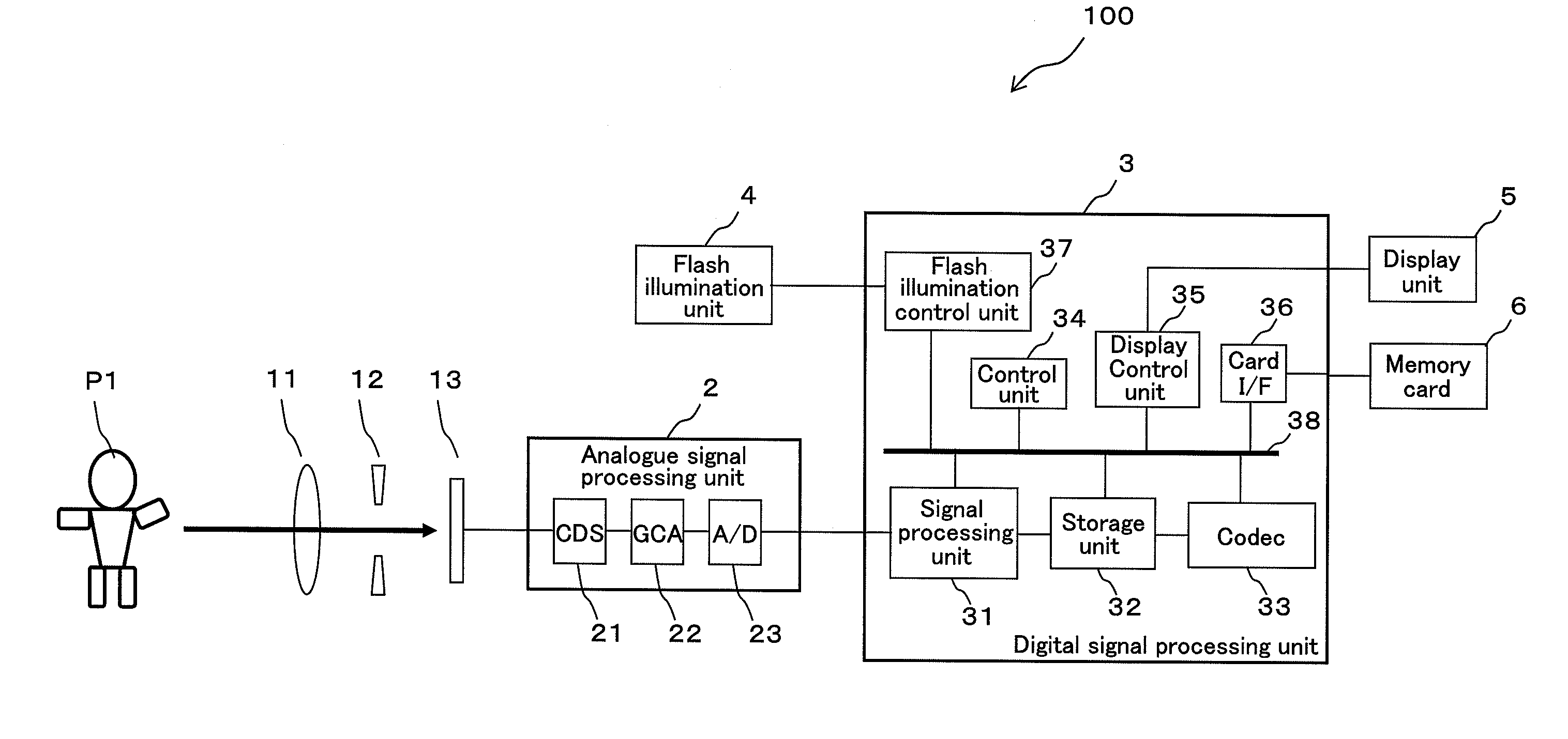
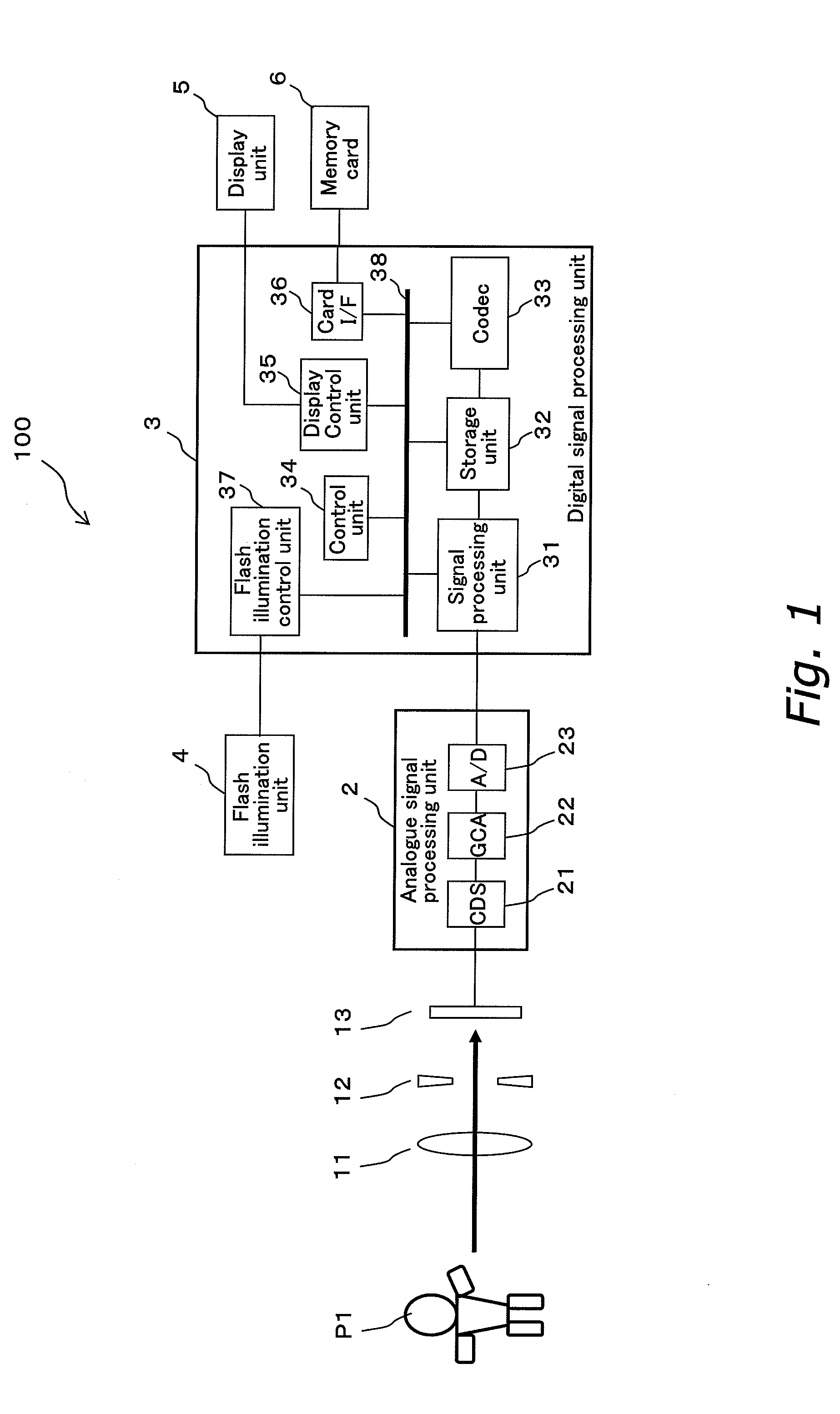
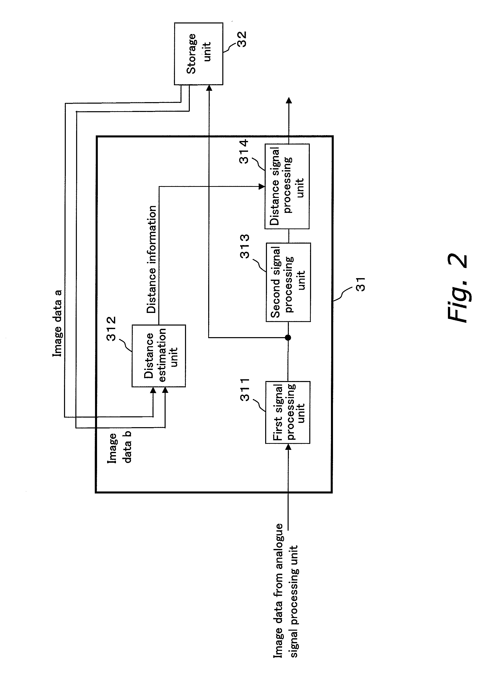
[0073]FIG. 1 is a schematic block diagram showing the structure of the imaging apparatus 100 (for example, a digital camera) according to the first embodiment. FIG. 2 is a schematic block diagram showing the structure of a signal processing unit 31 and a storage unit 32. FIG. 4 is a schematic block diagram showing the structure of a distance estimation unit 312.

[0074]As shown in FIG. 1, the imaging apparatus 100 includes an imaging lens 11, an aperture 12, an imaging unit (image sensor) 13, an analogue signal processing unit 2, a digital signal processing unit 3, and a flash illumination unit 4. The imaging lens 11 focuses light from a subject P1. The aperture 12 adjusts the amount of the light from the subject P1, which has been focused through the imaging lens 11. The imaging unit 13 converts the light from the subject P1 by photoelect...


PUM


Abstract

An imaging apparatus estimates a distance based on a reflectance value of a subject estimated with improved precision. An illumination unit illuminates a subject with illumination light. An imaging unit captures a plurality of images each under a different condition of the illumination unit. An illumination light element obtaining unit obtains an image formed with an element of the illumination light from the plurality of images. A reflectance estimation unit eliminates illumination variations from one of the plurality of images or from the image formed with the illumination light element, and estimates a reflectance of the subject corresponding to each pixel. A distance information estimation unit estimates a distance to the subject corresponding to each pixel based on the image formed with the illumination light element and the reflectance of the subject.

Description

BACKGROUND OF THE INVENTION[0001]1. Field of the Invention[0002]The present invention relates to an imaging apparatus, an imaging method, a program, a storage medium, and an integrated circuit for estimating distance information for each pixel of a captured image (the distance between a subject corresponding to the pixel and an image capturing position (camera installation position) in a three-dimensional space) using illumination.[0003]2. Description of the Related Art[0004]With the widespread of digital single-reflex cameras, many photographers enjoy expressing distance in their photographs. For such photographic expressions using distance, photographers may for example defocus and blur the background of an image by setting a faster shutter speed and a larger aperture to decrease the depth of field. However, compact digital cameras and video cameras have limitations in their lens sizes. With small lenses of compact digital cameras and video cameras, photographers cannot have satis...

Claims


Application Information

Patent Timeline
IPC IPC(8): H04N5/225G03B15/03H04N5/262H04N5/222
CPCG01S17/89G03B15/03H04N5/262G06T7/0073G06T2207/10152G06T5/50G06T7/586
Inventor SATO, DAISUKEYAMASHITA, HARUOITO, TAKESHI
Owner PANASONIC CORP
Learn More