Method and apparatus for determining the position of a moving object, by using visible light communication

a technology of visible light communication and position determination, applied in the field of position determination system, can solve the problems of high cost, inability to put into practical use a position determination system of this type, and the system that uses a plurality of cameras mounted on each vehicle, etc., and achieves the effect of convenient application

Inactive Publication Date: 2009-02-05
KK TOSHIBA
View PDF13 Cites 73 Cited by
  • Summary
  • Abstract
  • Description
  • Claims
  • Application Information

AI Technical Summary

Benefits of technology

[0009]An object of the present invention is to provide a position determination system tha

Problems solved by technology

Any system that uses a plurality of cameras mounted on each vehicle, however, is expensive due to not only the use of cameras, but also the use of an apparatus that performs co

Method used


Image

  • Method and apparatus for determining the position of a moving object, by using visible light communication
  • Method and apparatus for determining the position of a moving object, by using visible light communication
  • Method and apparatus for determining the position of a moving object, by using visible light communication

Examples


Embodiment Construction

[0020]An embodiment of the present invention will be described with reference to the accompanying drawings.

[0021](Configuration of the System)

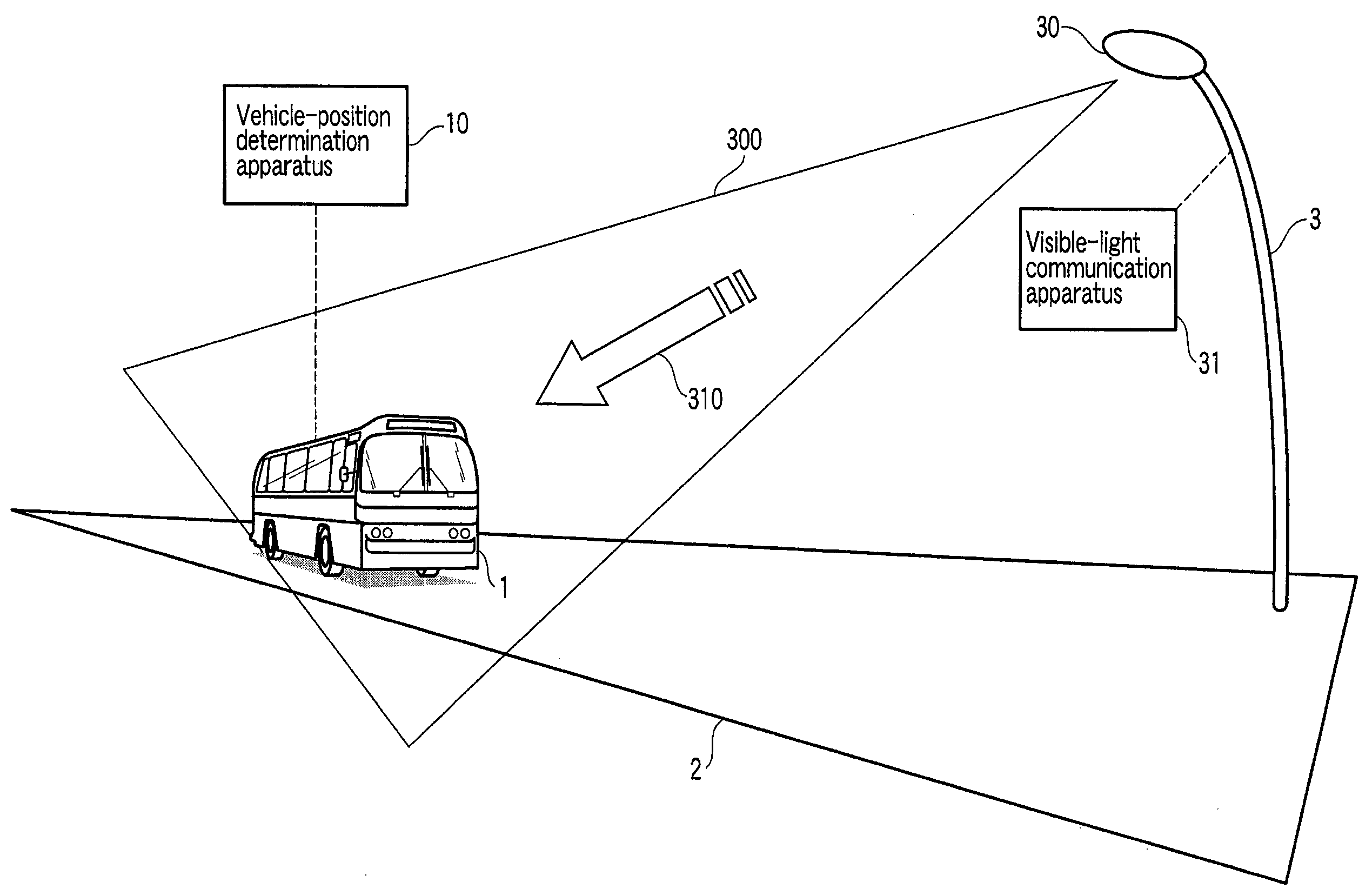
[0022]FIG. 1 is a diagram showing the major components of a position determination system according to an embodiment of the invention.

[0023]The embodiment is a system that determines the present position of an automobile (hereinafter referred to as vehicle) 1, by utilizing a visible-light communication system. The major components of the system are: a lamp post 3 and a position determination apparatus 10. The lamp post 3 stands on one side of a road 2 on which the vehicle 1 is running. The position determination apparatus 10 (hereinafter called vehicle position determination apparatus) is mounted on the vehicle 1.

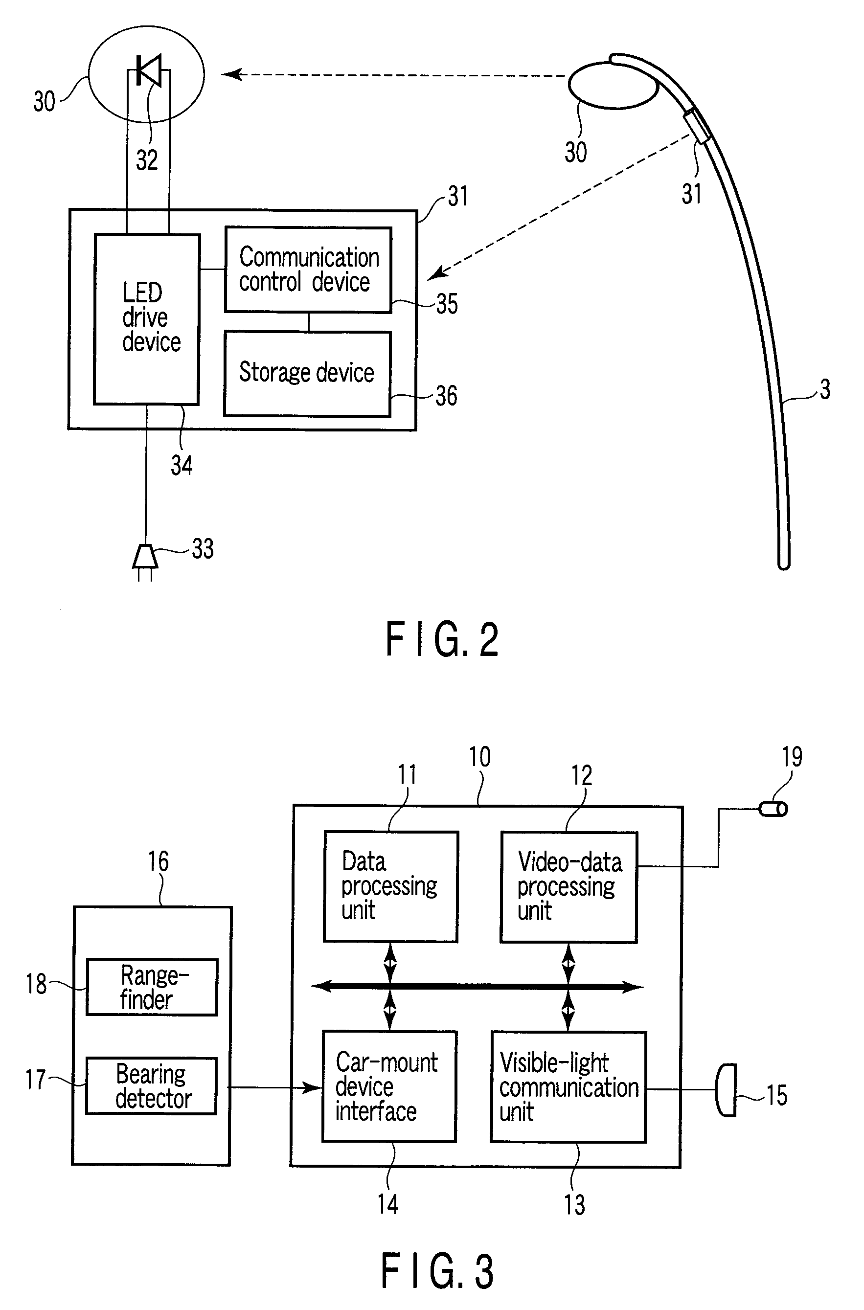
[0024]The lamp post 3 has a road-illumination lamp 30 and a visible-light communication apparatus 31. The lamp 30 illuminates the road 2. The lamp 30 has a light-emitting diode (hereinafter referred to as LED) and emits illumination l...


PUM


Abstract

An apparatus for determining the present position of a vehicle, by utilizing a visible-light communication system. The apparatus uses a visible-light communication beacon and video data representing an image photographed by one camera. The beacon emits a visible optical signal, thus transmitting position data. The visible-light communication beacon comprises a road-illuminating lamp and a visible-light communication apparatus, both secured to a lamp post. The vehicle has the camera and a vehicle position determination apparatus. The vehicle position determination apparatus demodulates the visible optical signal, there restoring the position data, and calculates the present position of the vehicle from the position data.

Description

CROSS-REFERENCE TO RELATED APPLICATIONS[0001]This application is based upon and claims the benefit of priority from prior Japanese Patent Application No. 2007-199543, filed Jul. 31, 2007, the entire contents of which are incorporated herein by reference.BACKGROUND OF THE INVENTION[0002]1. Field of the Invention[0003]The present invention generally relates to a position determination system that utilizes visible light communication. More particularly, the invention relates to a position determination system that determines the position of a moving object such as a vehicle.[0004]2. Description of the Related Art[0005]In recent years, position determination systems utilizing the global positioning system (GPS) have been widely used as system for determining the present position of a vehicle, a representative example of which is an automobile. Each position determination system of this type is incorporated in, for example, a car-navigation apparatus.[0006]Recently, position determinatio...

Claims


Application Information

Patent Timeline
IPC IPC(8): H04N5/228G06K9/00G01C3/06G01S1/70G01S3/782G01S5/16H04B10/11H04B10/116H04B10/118H04B10/54
CPCG01S1/70G01S5/16G08G1/096783G08G1/096758G08G1/096716G01S2201/01G01S1/7038G01S1/7034G01S1/02
Inventor SHIMADA, SHIGEHITO
Owner KK TOSHIBA
Why Eureka
Try Eureka