Liquid Crystal Display Device

a display device and liquid crystal technology, applied in non-linear optics, instruments, optics, etc., can solve the problems of weak adhesion of adhesive or bonding material to resin plate, difficulty in reducing the thickness of the display part of a cellular phone, and lowering the visibility of displayed video or images

Active Publication Date: 2009-02-05
PANASONIC LIQUID CRYSTAL DISPLAY CO LTD +1
View PDF7 Cites 8 Cited by
  • Summary
  • Abstract
  • Description
  • Claims
  • Application Information

AI Technical Summary

Benefits of technology

[0025]In the liquid crystal display device according to the present invention, the resin plate (protective cover) which is attached to the upper polarization plate with the adhesive or bonding material can be made hard to become detached.

Problems solved by technology

This structure is beginning to make further thickness reduction of the display part of a cellular phone difficult, and has problems such as lowered visibility of displayed video or images due to a layer of air between the liquid crystal display panel and the protective cover.
Attaching the resin plate to the polarization plate with an adhesive or bonding material has a problem in that, if the adhesive or bonding material is the same acrylic resin-based adhesive or bonding material that is used to attach an upper polarization plate to an insulating substrate (glass substrate) constituting the opposite substrate, the adhesion of the adhesive or bonding material to the resin plate is weak and the resin plate becomes easily detached.

Method used


Image

  • Liquid Crystal Display Device
  • Liquid Crystal Display Device
  • Liquid Crystal Display Device

Examples


Embodiment Construction

[0043]The present invention will be described in detail below through an embodiment with reference to the drawings.

[0044]Throughout the drawings illustrating the embodiment, components having the same function are denoted by the same reference symbol in order to avoid repetitive description.

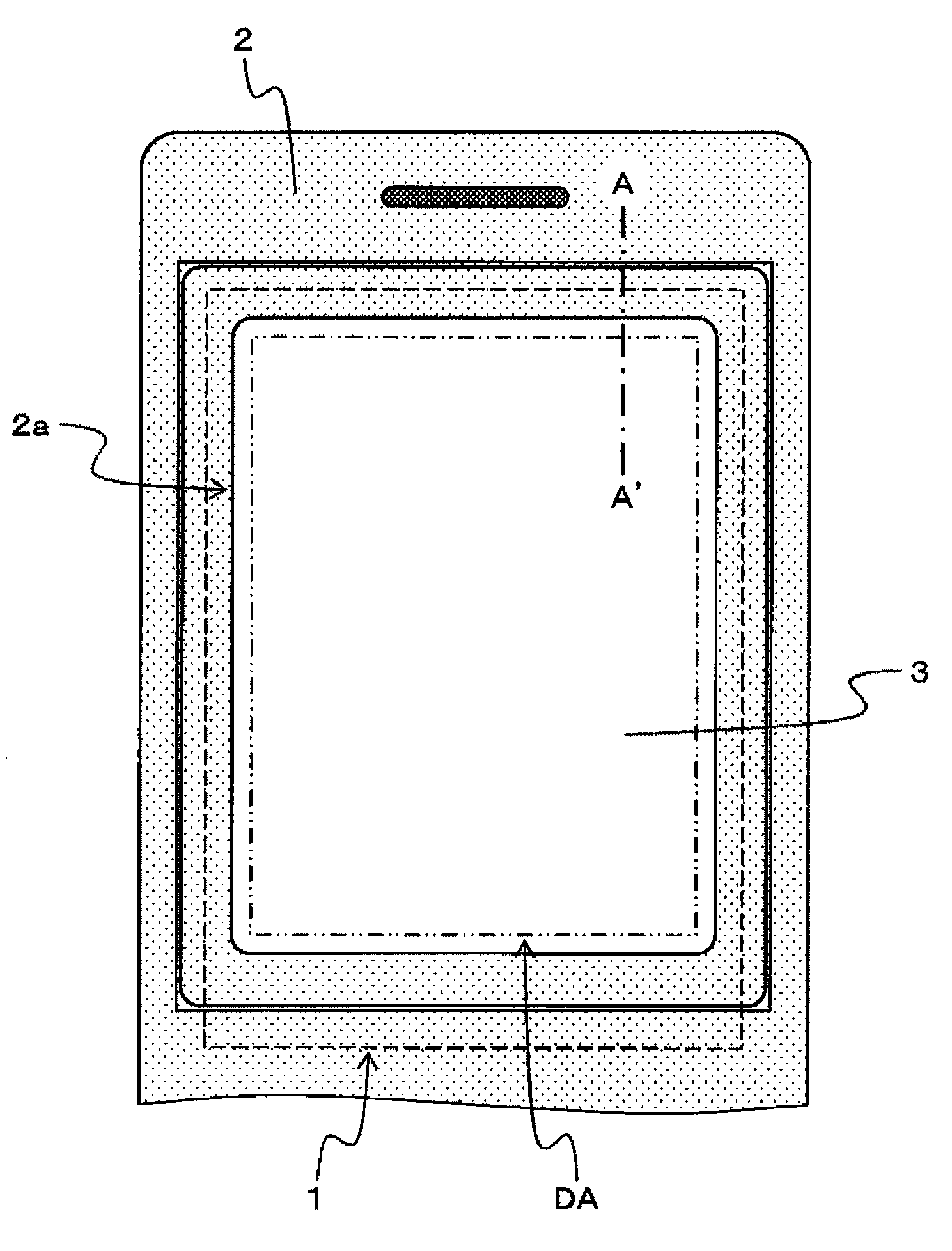
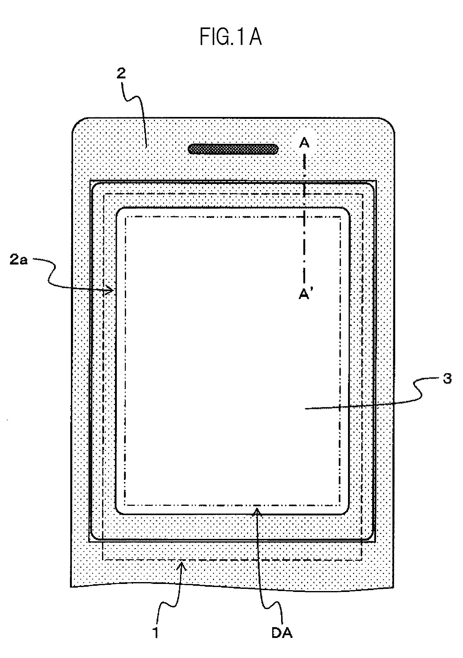
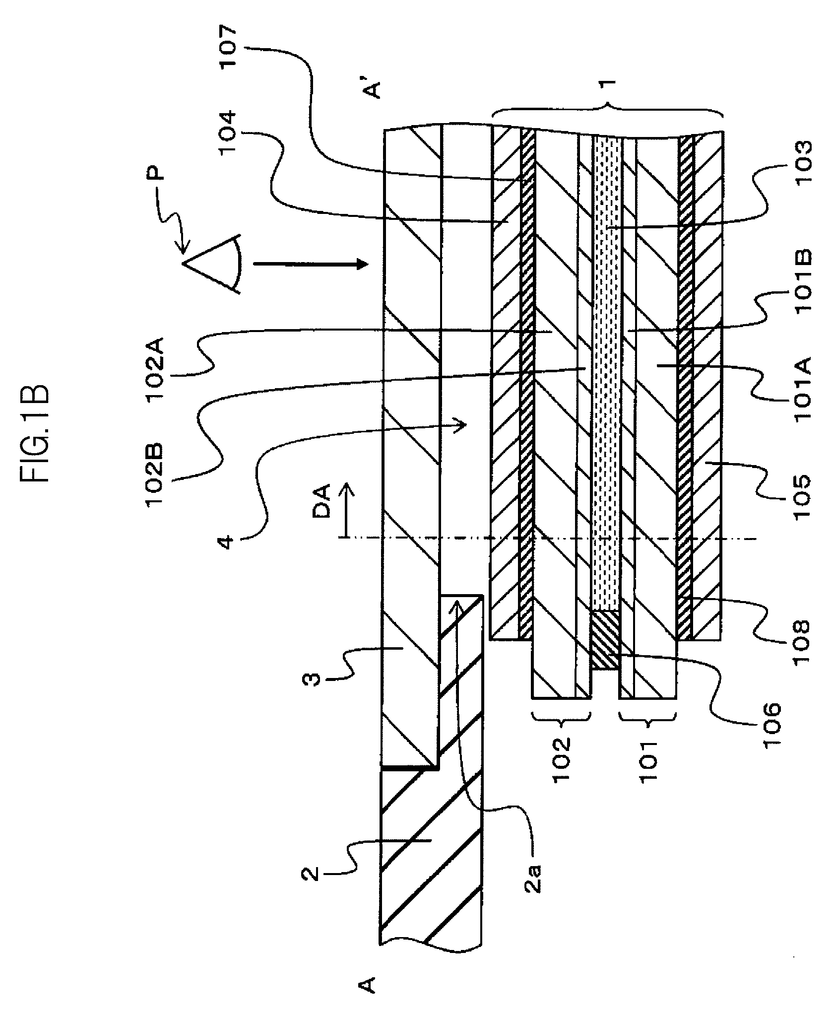
[0045]FIGS. 1A and 1B and FIGS. 2A and 2B are schematic diagrams outlining a conventional liquid crystal display device and a liquid crystal display device according to the present invention, respectively.

[0046]FIG. 1A is a schematic plan view showing an example of the schematic structure of a display part in a conventional cellular phone. FIG. 1B is a schematic sectional view taken along the line A-A′ of FIG. 1A.

[0047]FIG. 2A is a schematic plan view showing an example of the schematic structure of a display part in a cellular phone that has a liquid crystal display device according to the present invention. FIG. 2B is a schematic sectional view taken along the line B-B′ of FIG. 2A.

[0048]FIG. 1B...


PUM

PropertyMeasurementUnit
area DAaaaaaaaaaa
transparentaaaaaaaaaa
conductivityaaaaaaaaaa

Abstract

A liquid crystal display device includes: a first substrate; a second substrate which is placed nearer to a viewer than the first substrate, and which faces a viewer side of the first substrate; a liquid crystal sandwiched between the first substrate and the second substrate; an upper polarization plate which is placed nearer to the viewer than the second substrate, and which faces a viewer side of the second substrate; and a transparent resin plate which is placed nearer to the viewer than the upper polarization plate, and which is attached to a viewer side of the upper polarization plate with one of an adhesive material and a bonding material, the transparent resin plate includes a transparent oxide film on a face that faces the upper polarization plate, and the transparent resin plate is in close contact with the adhesive material or the bonding material through the transparent oxide film.

Description

CROSS-REFERENCE TO RELATED APPLICATION[0001]The present application claims priority from Japanese application JP 2007-201707 filed on Aug. 2, 2007, the content of which is hereby incorporated by reference into this application.BACKGROUND OF THE INVENTION[0002]1. Field of the Invention[0003]The present invention relates to a liquid crystal display device, and more particularly, to a technique effectively applied to a liquid crystal display device that is used as a display of a portable electronic device.[0004]2. Description of the Related Art[0005]Liquid crystal display devices are one of devices that have conventionally been used as a display of a portable electronic device such as a cellular phone and a personal digital assistant (PDA).[0006]Liquid crystal display devices are display devices that have a liquid crystal display panel in which a liquid crystal is sealed between a first substrate and a second substrate. The components of the liquid crystal display panel are arranged su...

Claims


Application Information

Patent Timeline
Patent Type & Authority Applications(United States)
IPC IPC(8): G02F1/1333
CPCG02F1/133528G02F2202/28
Inventor FUKUDA, KOICHIOSHIMA, TETSUYAKAWASAKI, SATORUSATO, TSUTOMUHAYAKAWA, KOUJI
Owner PANASONIC LIQUID CRYSTAL DISPLAY CO LTD
Why Eureka
Try Eureka