Generation of backing electric current on the basis of a combination of components

Active Publication Date: 2009-02-05
COVE DISTRIBUTION
View PDF12 Cites 17 Cited by
  • Summary
  • Abstract
  • Description
  • Claims
  • Application Information

AI Technical Summary

Problems solved by technology

When a sudden AC power failure occurs, the components of the PC stop working, causing the typical

Method used


Image

  • Generation of backing electric current on the basis of a combination of components
  • Generation of backing electric current on the basis of a combination of components
  • Generation of backing electric current on the basis of a combination of components

Examples


Example

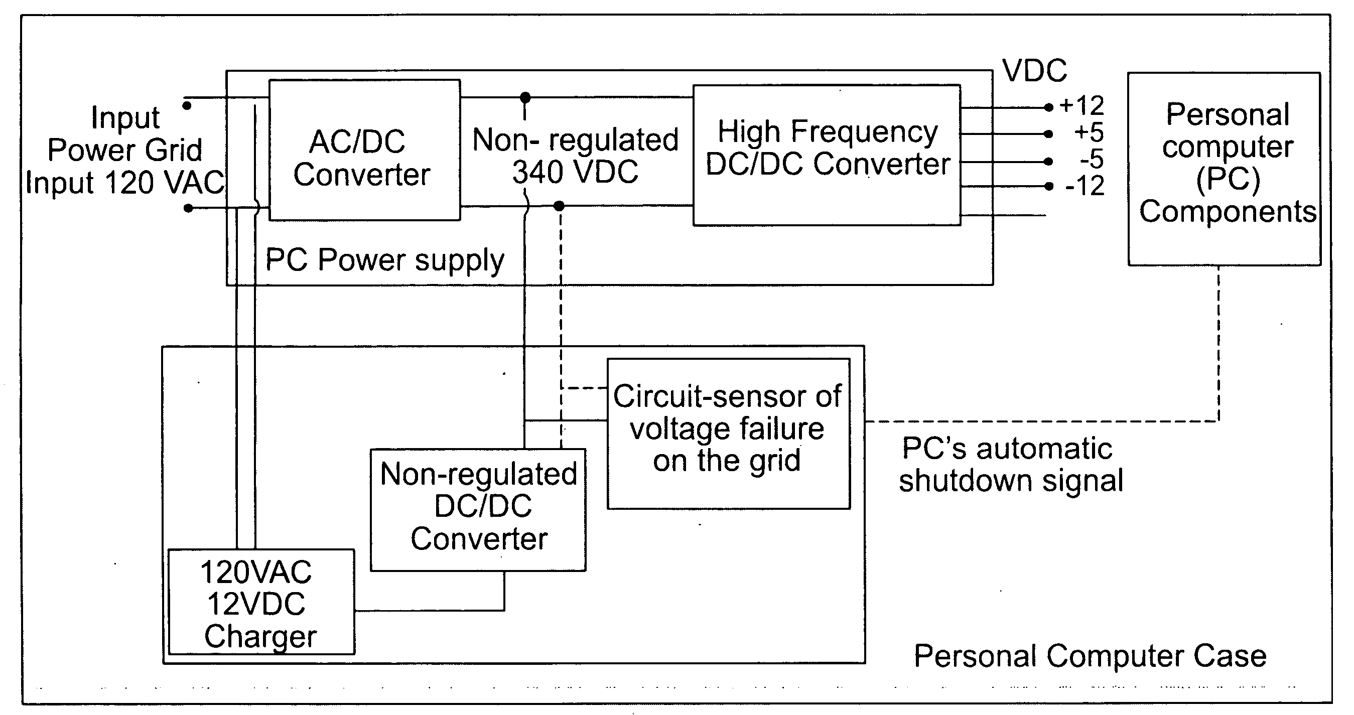
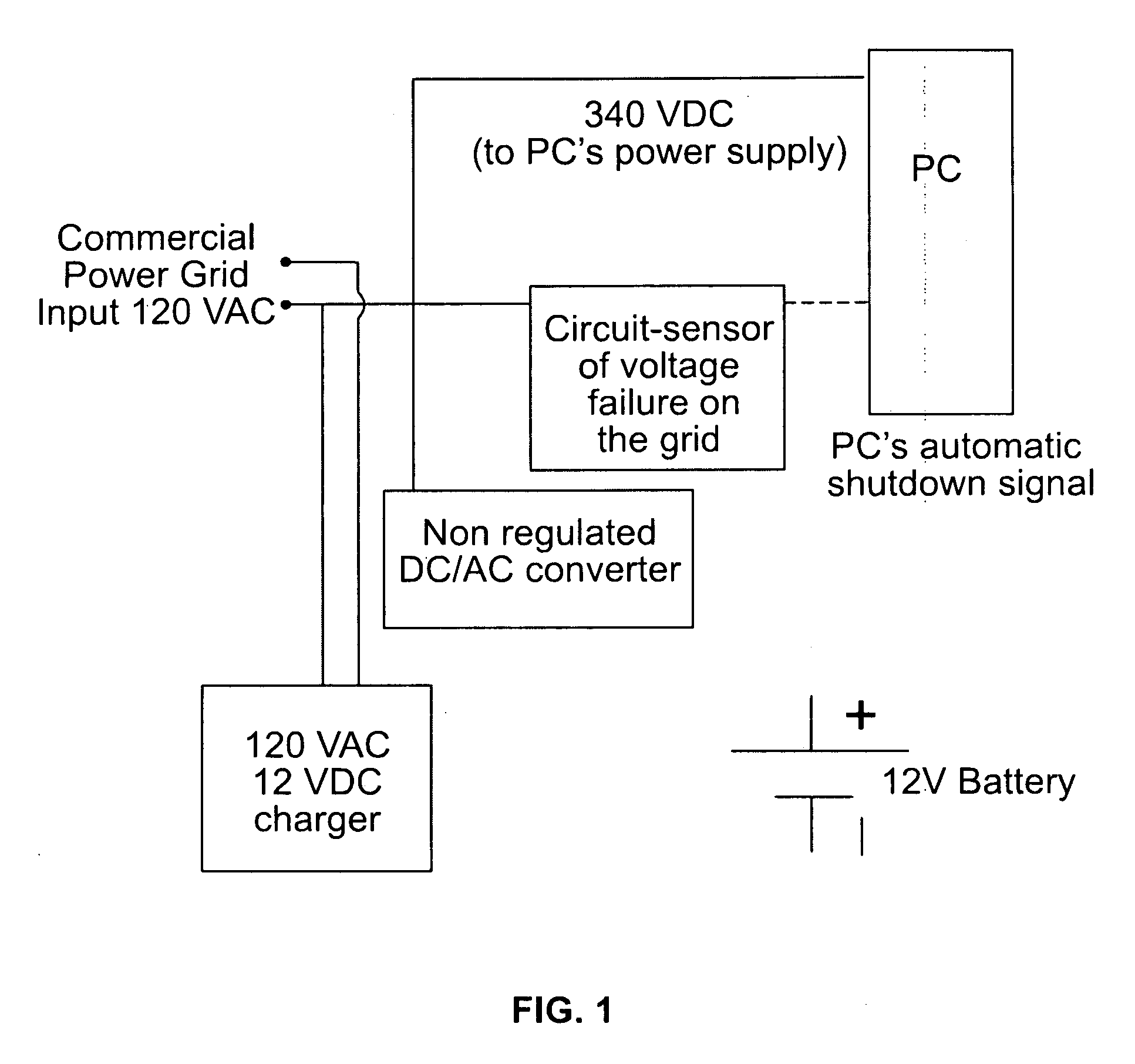
[0009]The integrated backup unit (URI) is shown in the FIGURE and it has 4 main elements: 1) A battery charger 10 of 120 VAC to 12 VDC; 2) A 12-V battery 15; 3) A DC / DC voltage converter 20; 4) A circuit 25 which detects voltage failures on the power grid outlet (120 VAC).

[0010]The battery charger 10 uses AC power directly from the 120-V electrical outlet 30 after it is connected to it. The charger output (12 VDC) then connects to the 12-volt battery 15. As long as there is voltage in the power grid outlet, the battery 15 will be charged permanently by the charger 10.

[0011]Voltage from the 12-volt battery 15 is then increased to a voltage of 340 VDC by the DC / DC converter 20. The converter's output is not regulated; therefore, it can have a voltage fluctuation of about 15%. As explained below, this non-regulated voltage has the appropriate characteristics to be combined with the PC's power supply in order to provide the desired backup functionality.

[0012]The circuit-sensor 25 of vol...


PUM


Abstract

This descriptive document is about a new backup device that takes advantage of the components of a PC's conventional power supply and it combines them with additional typical electronic components from an uninterruptible power supply (UPS). The result of such combination is a lower cost backup function that is applied directly to the PC and, therefore, eliminates the requirement of external devices—such as a UPS—to perform this backup function.
    • In this document, the electronic components that combine with the PC's power supply in order to provide the backup functionality described above are referred to as integrated backup unit (URI).

Description

CROSS-REFERENCE TO RELATED APPLICATION[0001]This application claims priority of Venezuelan Patent Application No. 1643-07 filed Jul. 31, 2007.[0002]Please replace the prior submitted substitute specification (November 8, 2007) with the substitute specification as follows:FIELD OF THE INVENTION[0003]The subject invention relates to personal computers and more specifically to a backup power supply for a personal computer.TECHNICAL BACKGROUND[0004]It is well known that the personal computer (PC) plays a main role as work's everyday tool. For the PC to be functional, all its components (including processor, storage drives, and memory) must receive power. This power comes from the commercial electric outlet (120 VAC).[0005]When a sudden AC power failure occurs, the components of the PC stop working, causing the typical inconveniences associated with the loss of information or even physical damage to the components. The popular uninterruptible power supply (UPS) was created to address thi...

Claims


Application Information

Patent Timeline
IPC IPC(8): G06F1/26G06F11/07G06F11/30
CPCG06F11/2015G06F1/30
Inventor ADAMS, MARY LOUISE
Owner COVE DISTRIBUTION
Why Eureka
Try Eureka