Engine blower

a technology of engine blower and blower body, which is applied in the direction of machines/engines, cleaning equipments, mechanical apparatus, etc., can solve the problems of insufficient ineffective lowering of exhaust gas temperature, and achieve the effect of promoting the reduction of exhaust gas temperature and enhancing the ejector

Inactive Publication Date: 2009-02-12
HUSQVARNA ZENOAH
View PDF46 Cites 17 Cited by
  • Summary
  • Abstract
  • Description
  • Claims
  • Application Information

AI Technical Summary

Benefits of technology

[0013]According to the aspect of the invention, since the blow-off port is provided on the end of the guide portion, the guide portion can reliably guide the cooling air from the blown-off port to the outside-air introduction gap, so that an increased amount of air can be introduced into the cover hood to further enhance the ejector effects, thereby further promoting the reduction in the exhaust gas temperature.

Problems solved by technology

However, the rest of the exhaust gas will not be sufficiently cooled, so that the exhaust gas temperature cannot be effectively lowered.
Hence, when the temperature-raised cooling air is mixed with the exhaust gas by the ejector effects, the exhaust gas temperature may not be sufficiently lowered.

Method used


Image

  • Engine blower
  • Engine blower
  • Engine blower

Examples


Embodiment Construction

)

[0018]An embodiment of the present invention will be described below with reference to the drawings.

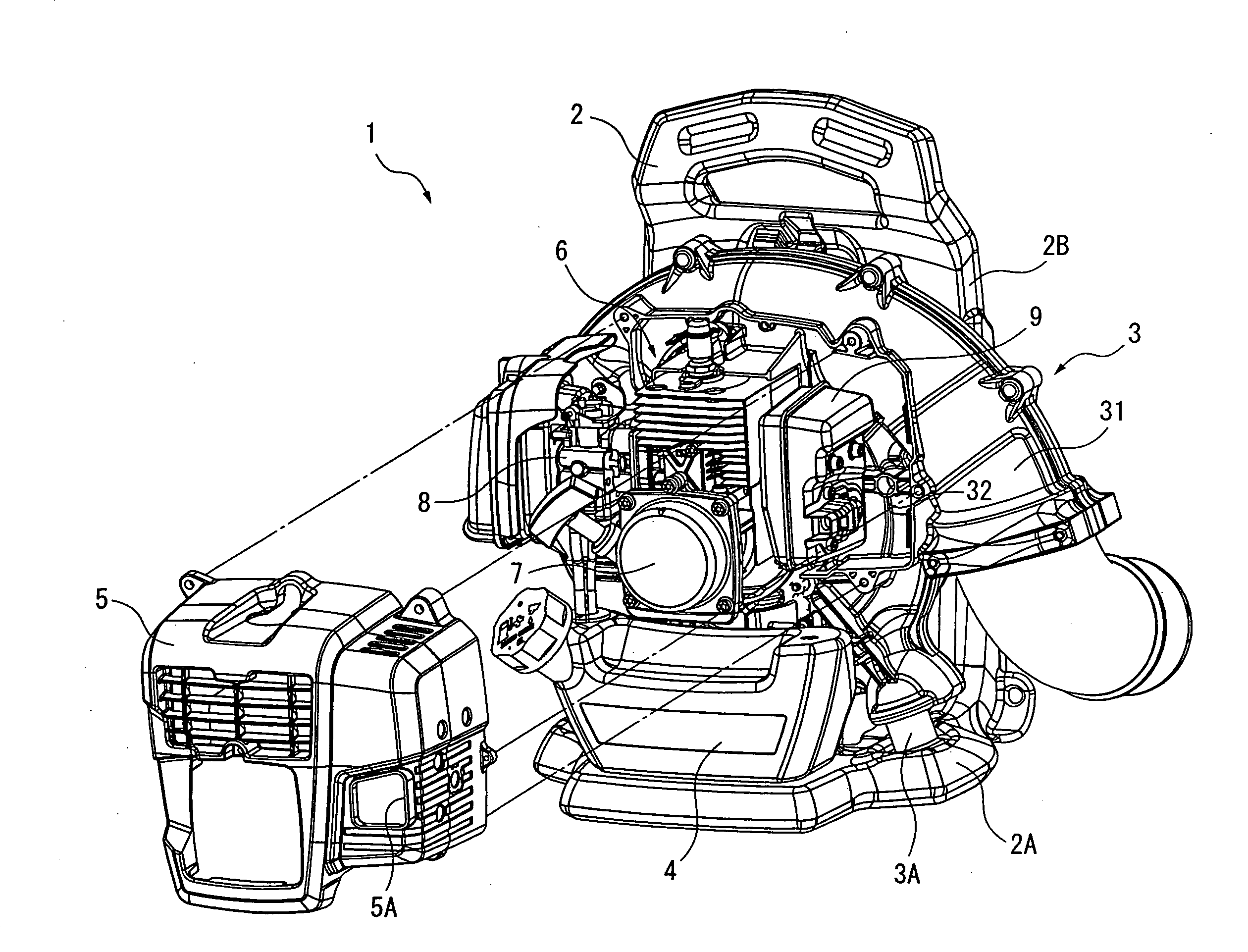
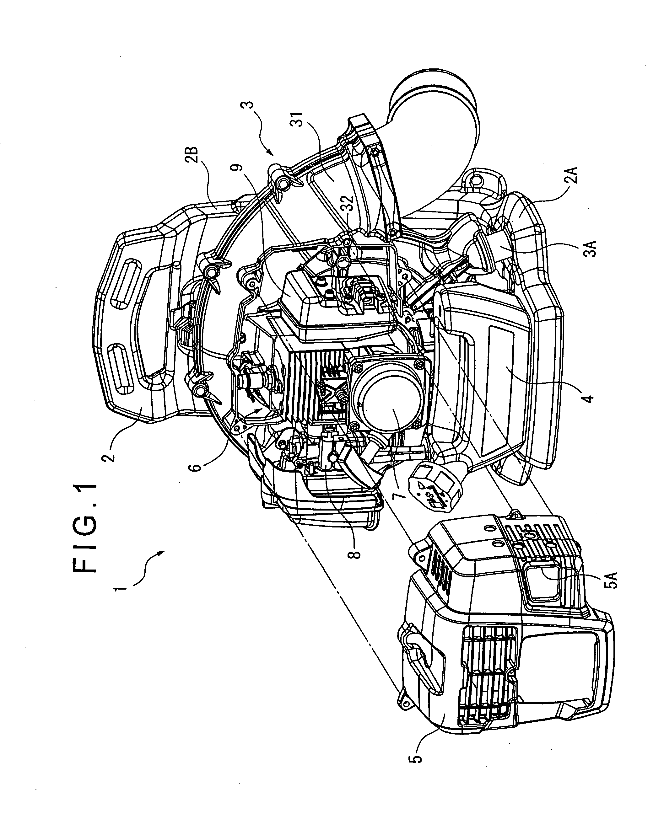
[0019]FIG. 1 is a partially-exploded perspective view of an entire engine blower 1 according to the embodiment.

[0020]In FIG. 1, the engine blower 1 includes an L-shaped frame 2 made of synthetic resin having a horizontal mounting portion 2A and a vertical back support 2B. A blower 3 is mounted on the mounting portion 2A of the frame 2 via a rubber mount 3A and supported at two positions on the right and left (only one of which is illustrated in FIG. 1). The blower 3 is also connected to the back support 2B via a connecting member (not shown).

[0021]A fuel tank 4 is also mounted on the mounting portion 2A, from which fuel is supplied to an engine 6 attached in front of a volute case 31 of the blower 3. The engine 6 rotates a fan (not shown) accommodated in the volute case 31. Pressure air generated by the rotation of the fan is ejected from a nozzle provided at an end of an air pipe co...


PUM


Abstract

An engine blower includes a muffler (9) provided to an engine and a volute case (31) accommodating a fan driven by the engine. On a muffler main body (10) of the muffler (9), an exhaust-gas guide member (21) covering an exhaust-gas outlet port and a cover hood (22) covering the exhaust-gas guide member (21) on the side of the outlet port are provided. Between the exhaust-gas guide member (21) and the cover hood (22), an outside-air introduction gap (23) is formed, through which outside air is introduced into the cover hood (22) by ejector effects. A blow-off port (32) for blowing off a part of pressure air in the volute case (31) to the outside-air introduction port (23) is only provided at a position substantially on a back side of the outside-air introduction gap (23).

Description

BACKGROUND OF THE INVENTION[0001]1. Field of the Invention[0002]The present invention relates to an engine blower, specifically to an improvement in a cooling structure for exhaust gas exhausted from an engine.[0003]2. Description of Related Art[0004]Engine blowers for blowing and collecting fallen leaves as well as pruned branches and leaves have been known. Such engine blower is carried by an operator in use and may be subject to regulations in terms of a temperature of exhaust gas from a muffler for eco-friendliness. Low-temperature discharge has been requested for the engine blower.[0005]To lower the exhaust gas temperature, air may be taken in from outside to be mixed with the exhaust by jet flow of the exhaust gas. Specifically, an exhaust-gas guide member for discharging exhaust gas from a muffler main body in a predetermined direction is provided on a surface of the muffler main body. The exhaust-gas guide member is covered by a cover hood. Owing to ejector effects by the ex...

Claims


Application Information

Patent Timeline
Patent Type & Authority Applications(United States)
IPC IPC(8): E01H1/08F02B63/02
CPCE01H1/0809F02B63/02F01N2590/06F01N1/14
Inventor WADA, SHINICHIZAMA, RYOUJIMIYAZAWA, KOUEYOSHINO, JUNICHI
Owner HUSQVARNA ZENOAH
Why Eureka
Try Eureka