Endotracheal Tube and Intubation System Including Same

Active Publication Date: 2009-02-12
HOSPITECH RESPIRATION
View PDF82 Cites 63 Cited by
  • Summary
  • Abstract
  • Description
  • Claims
  • Application Information

AI Technical Summary

Benefits of technology

[0005]An object of the present invention is to provide an endotracheal tube, and also an intubation system, having advantages in the above respects. Another object of the invention is to provide such a tube and intubation syste

Problems solved by technology

In studying the above problem, it was further noted that the negative pressure exerted by the suction lumen caused the creation of

Method used


Image

  • Endotracheal Tube and Intubation System Including Same
  • Endotracheal Tube and Intubation System Including Same
  • Endotracheal Tube and Intubation System Including Same

Examples


Embodiment Construction

The Intubation System of FIGS. 1-5

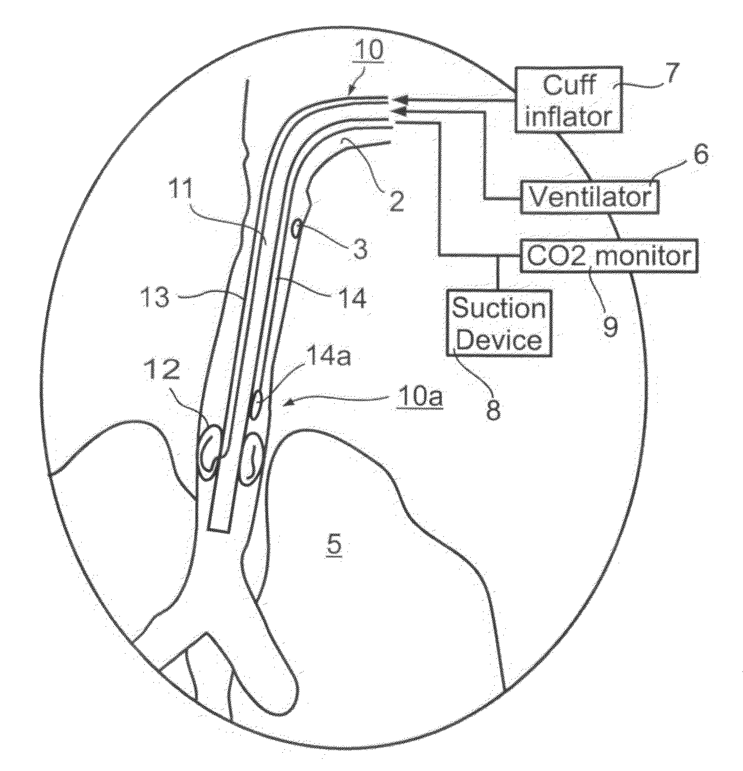
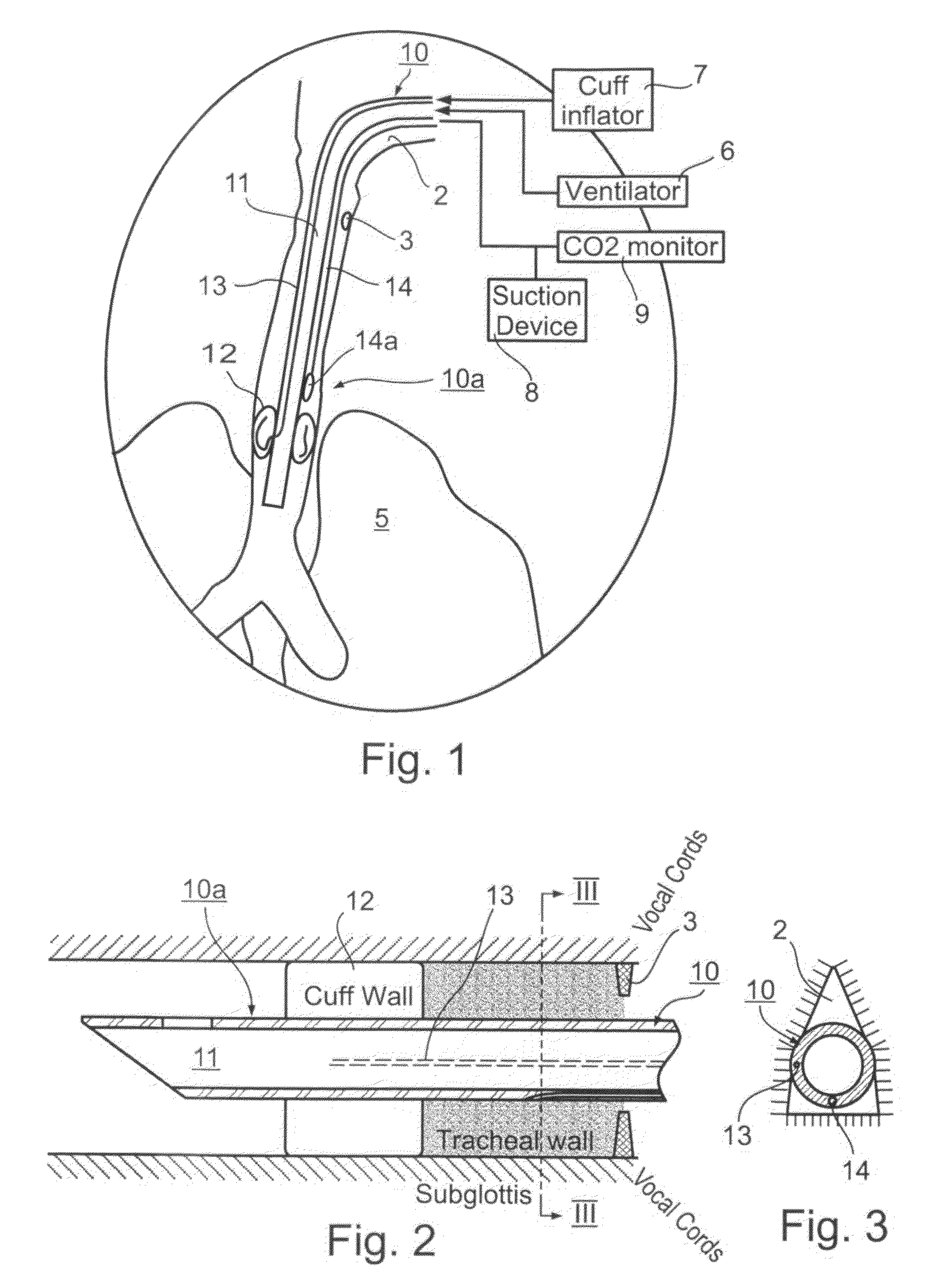
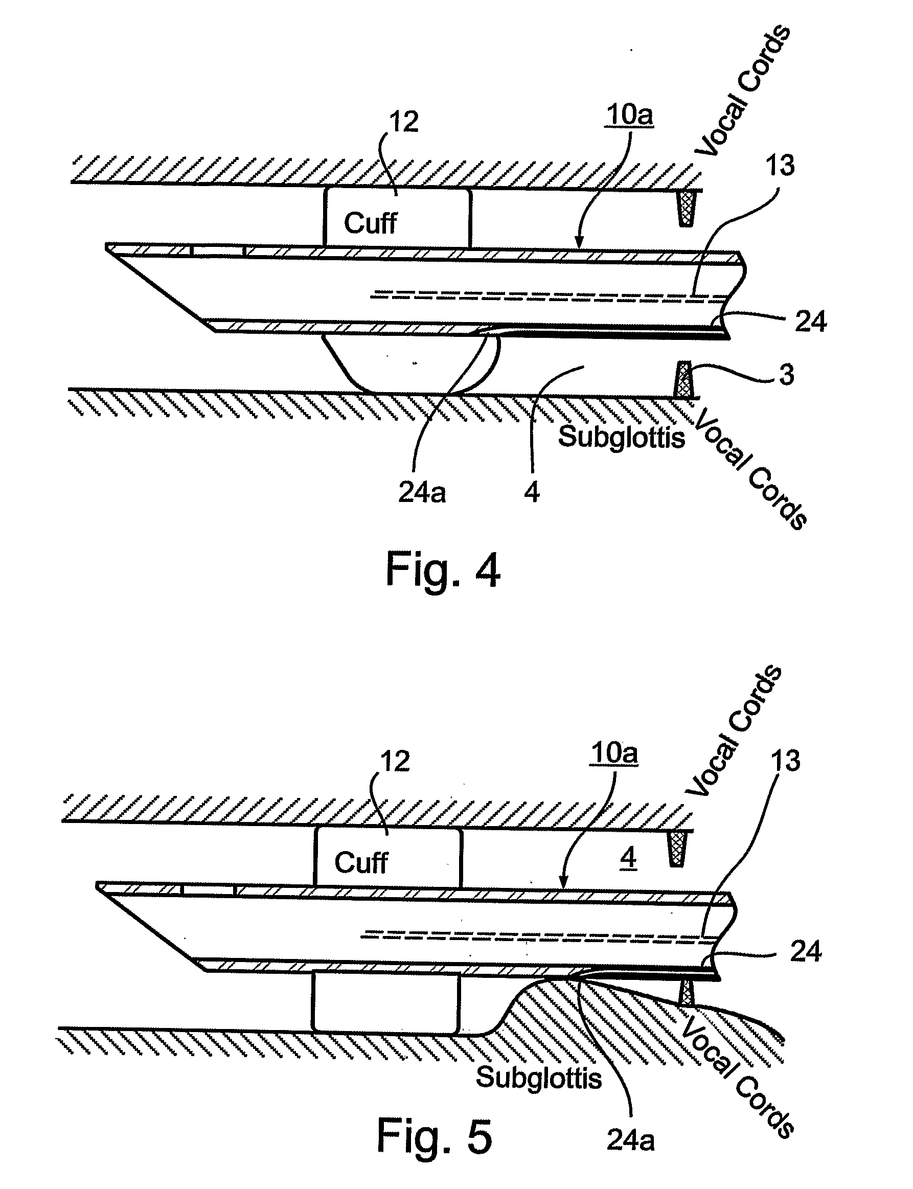
[0036]The preferred embodiments of the present invention to be described below relate primarily to the type of intubation system for mechanically ventilating patients as illustrated in FIGS. 1-3. Such a system utilizes an endotracheal tube, generally designated 10, having a distal end 10a for insertion into the patient's airway 2, past the vocal chords 3, through the subglottal region 4 and into the patient's lungs 5. The proximal end 10b of endotracheal tube 10 is connectable to a mechanical ventilator 6, as well as to a number of control devices as will be described more particularly below.

[0037]As indicated earlier, such endotracheal tubes generally include a main lumen 11 for ventilating the patient, and a cuff 12 at the distal end 10a of the tube to be located in the subglottal region 4 of the patient, below the vocal chords. Such tubes also include an inflating lumen 13 extending through the tube for inflating the cuff by a cuff inflator 7 at ...


PUM


Abstract

An endotracheal tube for mechanically ventilating patients is disclosed. The endotracheal tube comprises a distal end for insertion into the patient's airway, past the vocal chords, through the subglottal region, and into the patient's lung; and a proximal end for connection to a mechanical ventilator. The endotracheal tube further comprises a cuff at the distal end of the endotracheal tube to be located in the subglottal region of the patient below the vocal chords, an inflating lumen for inflating the cuff, and a suction lumen having a suction inlet port leading from the outer surface of the endotracheal tube, and to be located in the subglottal region, for evacuating secretions and/or rinsing fluid from the subglottal region during the mechanical ventilation of the patient. The distal end of the endotracheal tube is formed with an outer surface configuration effective to prevent blockage of the suction inlet port by the cuff or by tracheal mucosal tissue of the patient during a negative pressure condition in the suction lumen.

Description

FIELD AND BACKGROUND OF THE INVENTION[0001]The present invention relates to endotracheal tubes for mechanically ventilating patients, and also to an intubation system including such tubes.[0002]In the medical treatment of patients requiring breathing assistance, it is frequently necessary to insert an endotracheal tube into the trachea of the patient, by way of the mouth or nose and to connect the tube to a ventilator which periodically forces air into the lungs through the tube. The inner or distal end of the tube is typically provided with an inflatable cuff which is inflated into contact with the interior wall of the trachea.[0003]In using such endotracheal tubes, however, problems arise with respect to bodily secretions which pass progressively between the inner surface of the trachea and the outer surface of the cuff. The evacuation of secretions accumulated in the subglottal region above the cuff is required to prevent a ventilator-associated lung infection, commonly called VA...

Claims


Application Information

Patent Timeline
IPC IPC(8): A61M16/04
CPCA61M16/0434A61M16/0463A61M16/0479A61M2205/32A61M2230/432A61M2205/15A61M2016/0413A61M16/0486A61M16/04A61M2230/005
Inventor EFRATI, SHAI
Owner HOSPITECH RESPIRATION
Why Eureka
Try Eureka