Rinsing methodologies for barrier plate and venturi containment systems in tools used to process microelectronic workpieces with one or more treatment fluids, and related apparatuses

a technology of venturi containment and barrier plate, which is applied in the direction of cleaning process and apparatus, cleaning using liquids, chemistry apparatus and processes, etc., can solve the problems of particle contamination, duct system is extremely compact, resultant spray has a tendency to splash when impacting the barrier structure, etc., and achieves efficient rinsing of wetted surfaces. , the effect of reducing the risk of generating particle contamination

Active Publication Date: 2009-02-12
TEL EPION
View PDF98 Cites 23 Cited by
  • Summary
  • Abstract
  • Description
  • Claims
  • Application Information

AI Technical Summary

Benefits of technology

[0009]The present invention provides a tool for treating microelectronic workpieces with one or more treatment materials, including liquids, gases, fluidized solids, dispersions, combinations of these, and the like. The invention provides an approach for rapid, efficient rinsing of wetted surface(s), and is particularly advantageous when used to rinse the lower surface of moveable barrier structures such as a barrier plate that overlies a workpiece being treated in such a manner to define a tapering flow channel over the workpiece. Rather than spray rinsing liquid onto the surface in a manner that generates undue splashing, droplet, or mist generation, the liquid is flowingly dispensed or poured, preferably under laminar flow conditions, onto a surface that is in fluid communication with the surface to be rinsed. A smooth, uniform wetting and sheeting action results to accomplish rinsing with a significantly reduced risk of generating particle contamination. In representative embodiments, the orifices through which the liquid is dispensed are in close proximity to the target surface, e.g., within 0.1 to 20, more desirably 0.1 to 5 mm, and even 1 mm from the target surface.
[0010]Additionally, embodiments of the present invention may incorporate a nozzle pattern that promotes very comprehensive wetting and smooth sheeting action of the lower barrier structure surface with less formation of discrete channels, dripping, or other problems that could lead to contamination. In these embodiments, the nozzle array(s) include at least one of, preferably two of, and more preferably all three of a variable spacing, varying nozzle size, and varying nozzle angle with respect to the surface targeted by the nozzles. A representative array of nozzles has variable spacing between nozzles and has two or more nozzles whose compound angle differs relative to one or more other nozzles in the array. Further, embodiments of the present invention may incorporate a pre-wetting strategy that promotes very comprehensive wetting and smooth sheeting action of the lower barrier structure surface with less of formation of discreet channels, dripping, or other problems that could lead to contamination.

Problems solved by technology

Because of the nested character of the duct structures, the duct system also is extremely compact.
Firstly, during the course of treating a workpiece, the lower surface of the barrier structure may bear drops or films of liquid(s) used during the treatment and / or as a result of rinsing the barrier structure.
While this strategy effectively rinses the barrier structure, the resultant spray has a tendency to splash when impacting the barrier structure.
This can generate droplets or mists that, in turn, can lead to particle contamination.
The alignment and spray pattern of the nozzles with the lower surface of the barrier structure can be difficult to set or maintain to match the geometry of the barrier structure.
The tubes and nozzles can collect moisture, which can drip and cause contamination.
The tubes and nozzles can also obstruct and / or disrupt the flow of liquids and gases into the process chamber.

Method used


Image

  • Rinsing methodologies for barrier plate and venturi containment systems in tools used to process microelectronic workpieces with one or more treatment fluids, and related apparatuses
  • Rinsing methodologies for barrier plate and venturi containment systems in tools used to process microelectronic workpieces with one or more treatment fluids, and related apparatuses
  • Rinsing methodologies for barrier plate and venturi containment systems in tools used to process microelectronic workpieces with one or more treatment fluids, and related apparatuses

Examples


Embodiment Construction

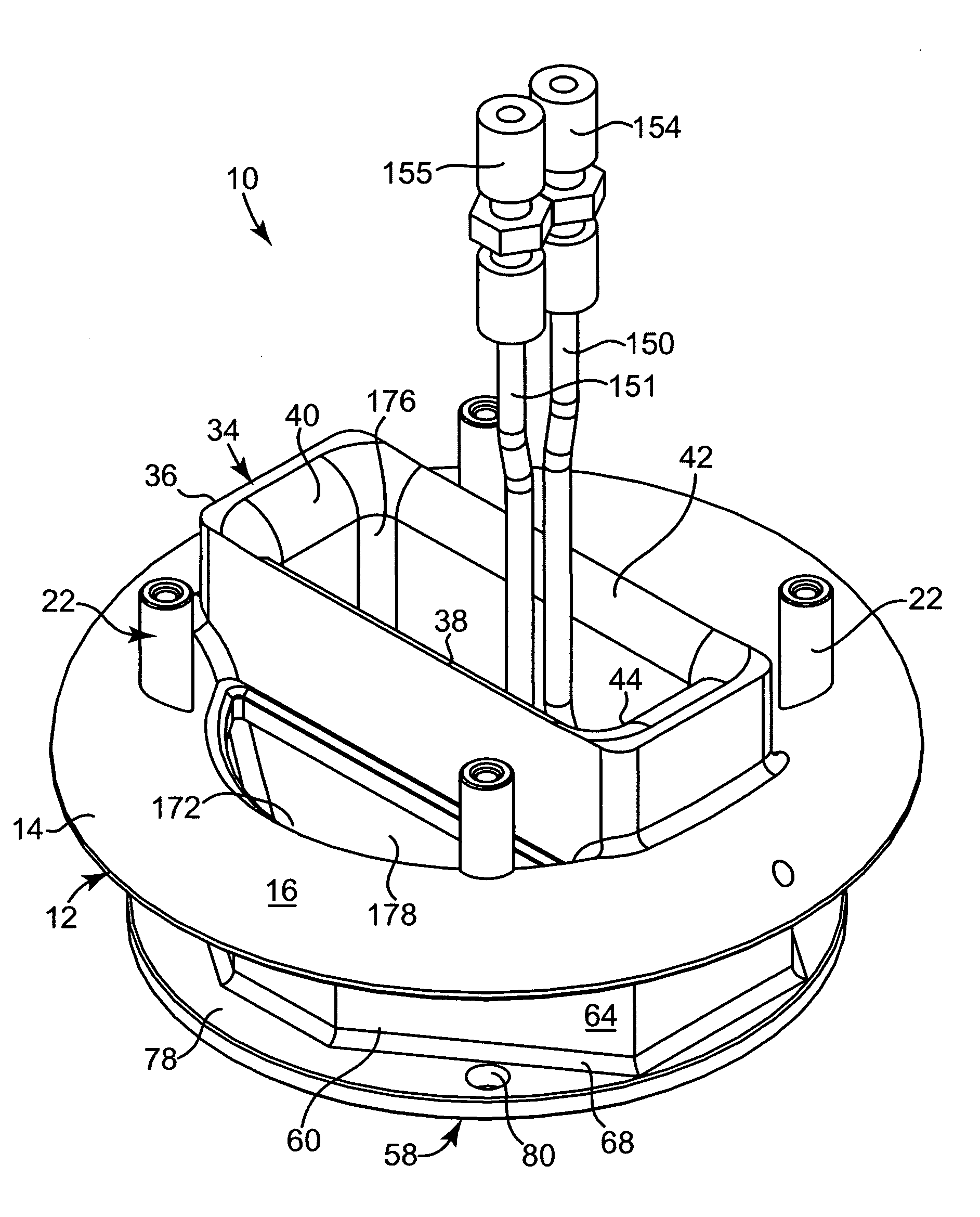
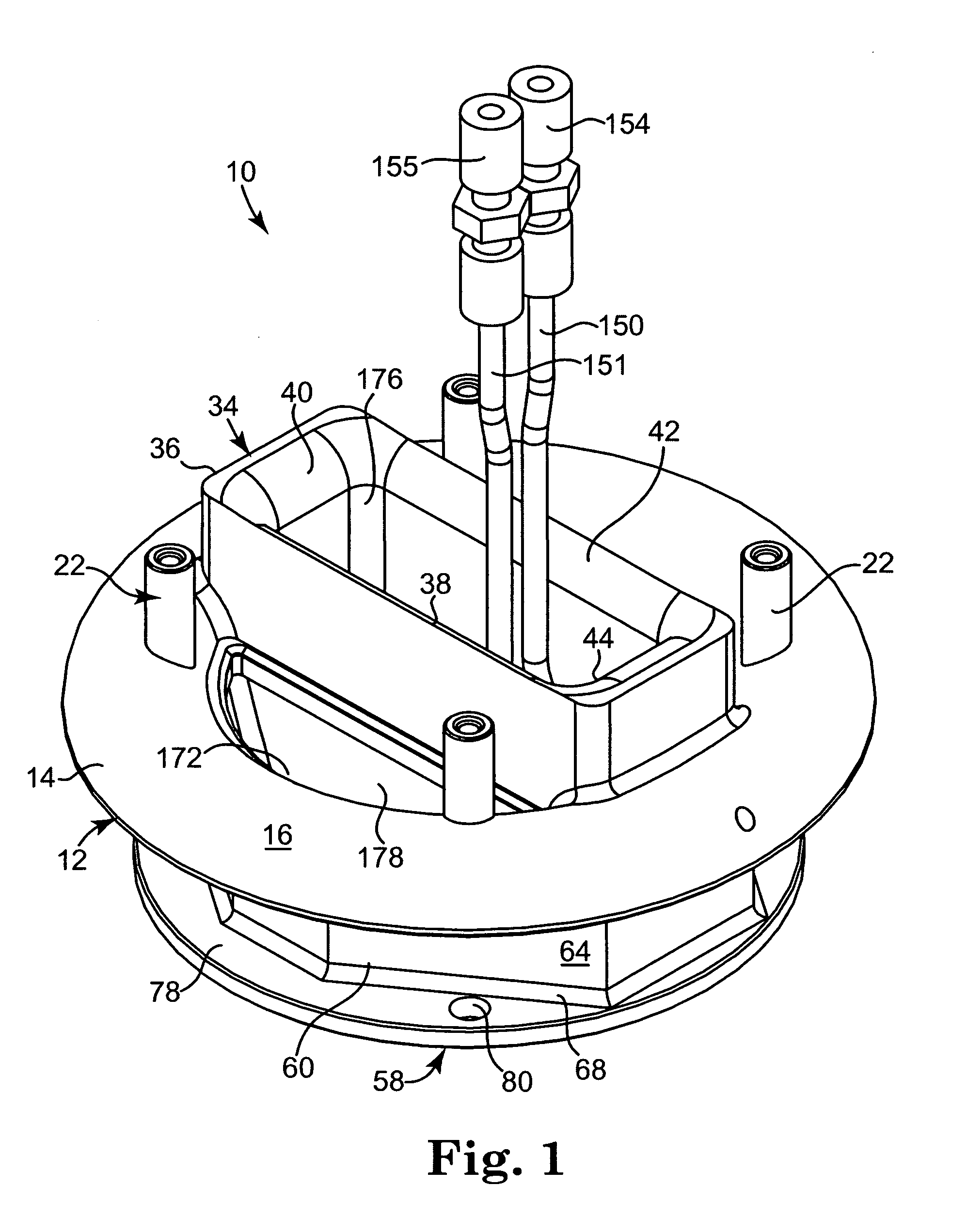
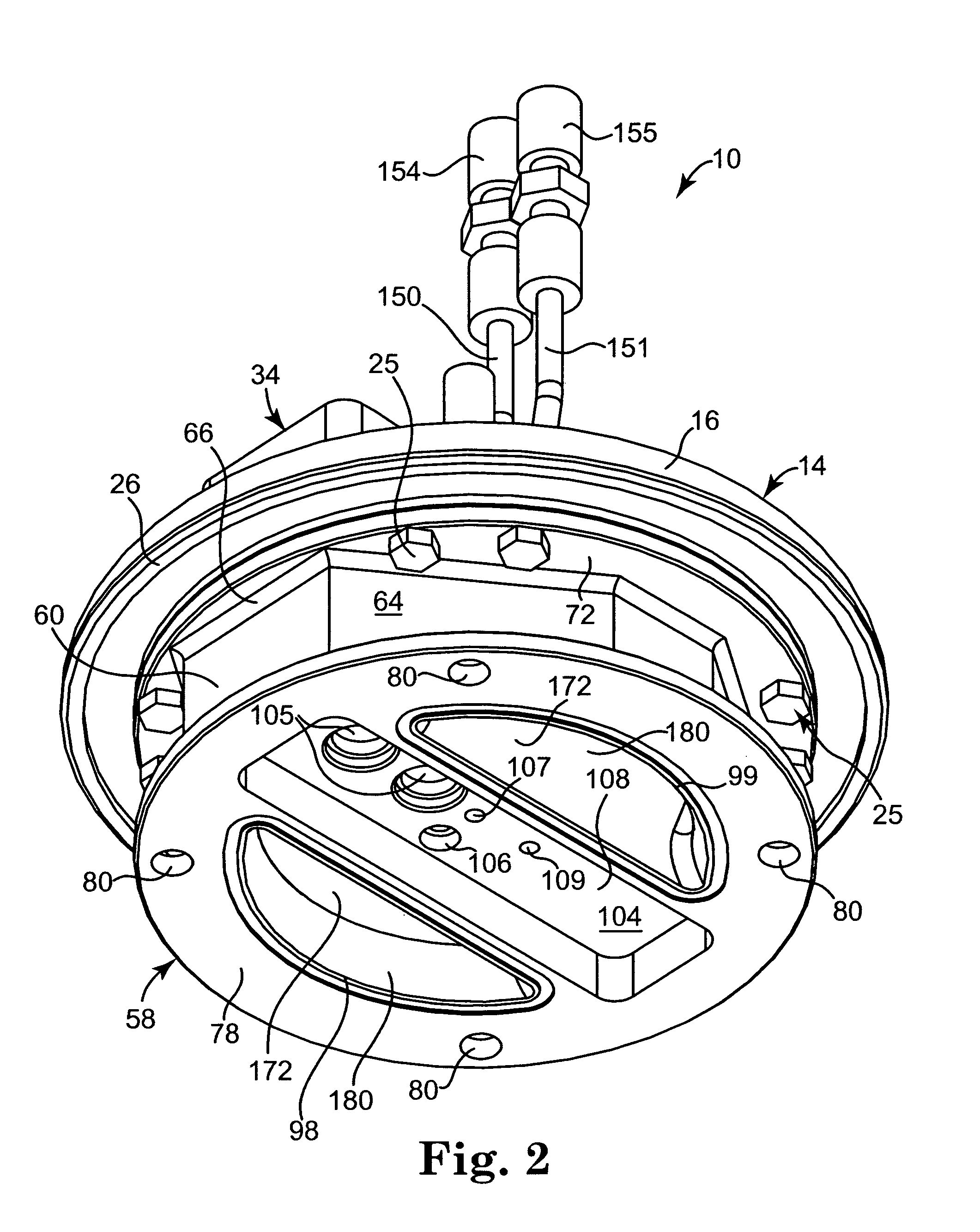
[0043]The embodiments of the present invention described below are not intended to be exhaustive or to limit the invention to the precise forms disclosed in the following detailed description. Rather the embodiments are chosen and described so that others skilled in the art may appreciate and understand the principles and practices of the present invention. While the present invention will be described in the specific context of fluid based microelectronic substrate cleaning systems, the principles of the invention are applicable to other microelectronic processing systems as well.

[0044]In the following discussion, if a recited feature and its reference numeral are both included in quotes, the recitation refers to a feature and reference numeral described and shown in Assignee's Co-Pending Application No. 3. If no quotes are used, the recitation refers to a feature and reference numeral of the present invention which will be shown in the accompanying Figures in addition to being des...


PUM


Abstract

Tool for treating microelectronic workpieces with one or more treatment materials, including liquids, gases, fluidized solids, dispersions, combinations of these, and the like. The invention provides an approach for rapid, efficient rinsing of wetted surface(s), and is particularly advantageous when used to rinse the lower surface of moveable barrier structures such as a barrier plate that overlies a workpiece being treated in such a manner to define a tapering flow channel over the workpiece. Rather than spray rinsing liquid onto the surface in a manner that generates undue splashing, droplet, or mist generation, the liquid is flowingly dispensed, preferably under laminar flow conditions, onto a surface that is in fluid communication with the surface to be rinsed. A smooth, uniform wetting and sheeting action results to accomplish rinsing with a significantly reduced risk of generating particle contamination.

Description

PRIORITY[0001]The present nonprovisional patent application claims priority under 35 USC § 119(e) from United States Provisional Patent Application having Ser. No. 60 / 963,840, filed on Aug. 7, 2007, by DeKraker et al., and titled RINSING METHODOLOGIES FOR BARRIER PLATE AND VENTURI CONTAINMENT SYSTEMS IN TOOLS USED TO PROCESS MICROELECTRONIC WORKPIECES WITH ONE OR MORE TREATMENT FLUIDS, wherein said provisional application is incorporated herein by reference in its entirety.FIELD OF THE INVENTION[0002]The present invention relates to barrier plates, venturi containment strategies, and dispense assemblies for tools used to process microelectronic substrates with one or more treatment fluids, including liquids and / or gases. More particularly, the present invention relates to such tools with improved rinsing capabilities with respect to the surfaces of the barrier plates and / or venturi-shaped containment pathways.BACKGROUND OF THE INVENTION[0003]The microelectronic industry relies on a ...

Claims


Application Information

Patent Timeline
Patent Type & Authority Applications(United States)
IPC IPC(8): B08B9/00B08B13/00
CPCH01L21/67051
Inventor DEKRAKER, DAVIDCOLLINS, JIMMY D.GAST, TRACY A.ROSE, ALAN D.WILLIAMSON, RICHARD E.
Owner TEL EPION
Why Eureka
Try Eureka