Heat element for maintaining laminator at predetermined working temperature

a predetermined working temperature and heating element technology, applied in the field of laminators, can solve the problems of long pre-heating time and inhomogeneous temperature of pressing rollers, poor laminating quality, and long pre-heating time longer than five minutes, and users' impatientness

Inactive Publication Date: 2009-02-12
MICHILIN PROSPERITY
View PDF2 Cites 11 Cited by
  • Summary
  • Abstract
  • Description
  • Claims
  • Application Information

AI Technical Summary

Benefits of technology

[0006]An objective of the invention is to provide a heating element that can maintain the laminator at a predetermined working temperature. By reducing the pre-heating time, the user can operate the laminator within the shortest possible time.
[0007]Another objective of the invention is to provide a heating element that can maintain the laminator at a predetermined working temperature. By providing a homogeneous pressing roller temperature, the user can obtain better laminating quality and avoid foggy bubbles due to low temperatures or burning due to high temperatures.

Problems solved by technology

In the above-mentioned laminating process, two problems that are complained the most by users are long pre-heating time and inhomogeneous pressing roller temperature.
The inhomogeneous pressing roller temperature results in bad laminating quality.
A pre-heating time longer than five minutes makes users impatient.

Method used


Image

  • Heat element for maintaining laminator at predetermined working temperature
  • Heat element for maintaining laminator at predetermined working temperature
  • Heat element for maintaining laminator at predetermined working temperature

Examples


first embodiment

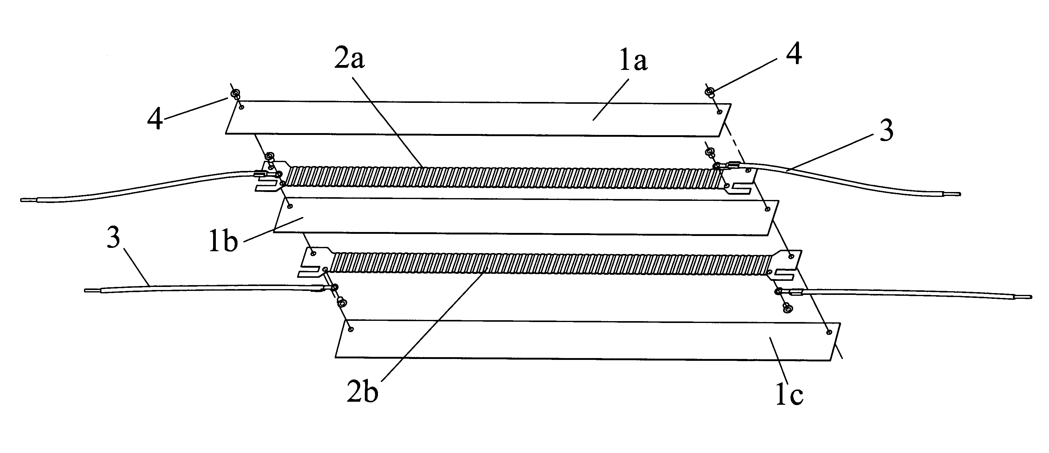
[0013]Please refer to FIG. 1, which shows the exploded three-dimensional structure of the disclosed heating element according to the The heating element includes top, middle, and bottom insulating materials such as mica sheets 1a, 1b, 1c and low-power heating filaments 2a and high-power heating filaments 2b arranged into a stripe shape and sandwiched between the mica sheets 1a, 1b, 1c. Both ends of the low-power heating filaments 2a and the high-power heating filaments 2b are connected with a power supply (not shown) via wires 3. The above-mentioned elements are fixed using, for example, rivets.

[0014]In practice, the high-power heating filaments 2b are shut down once it is heated to a predetermined high temperature. In this case, the low-power heating filaments 2a are turned on to maintain the laminator at a constant temperature for lamination. If the laminating temperature drops below a predetermined low temperature, the low-power heating filaments 2a are turned off, and the high-...

second embodiment

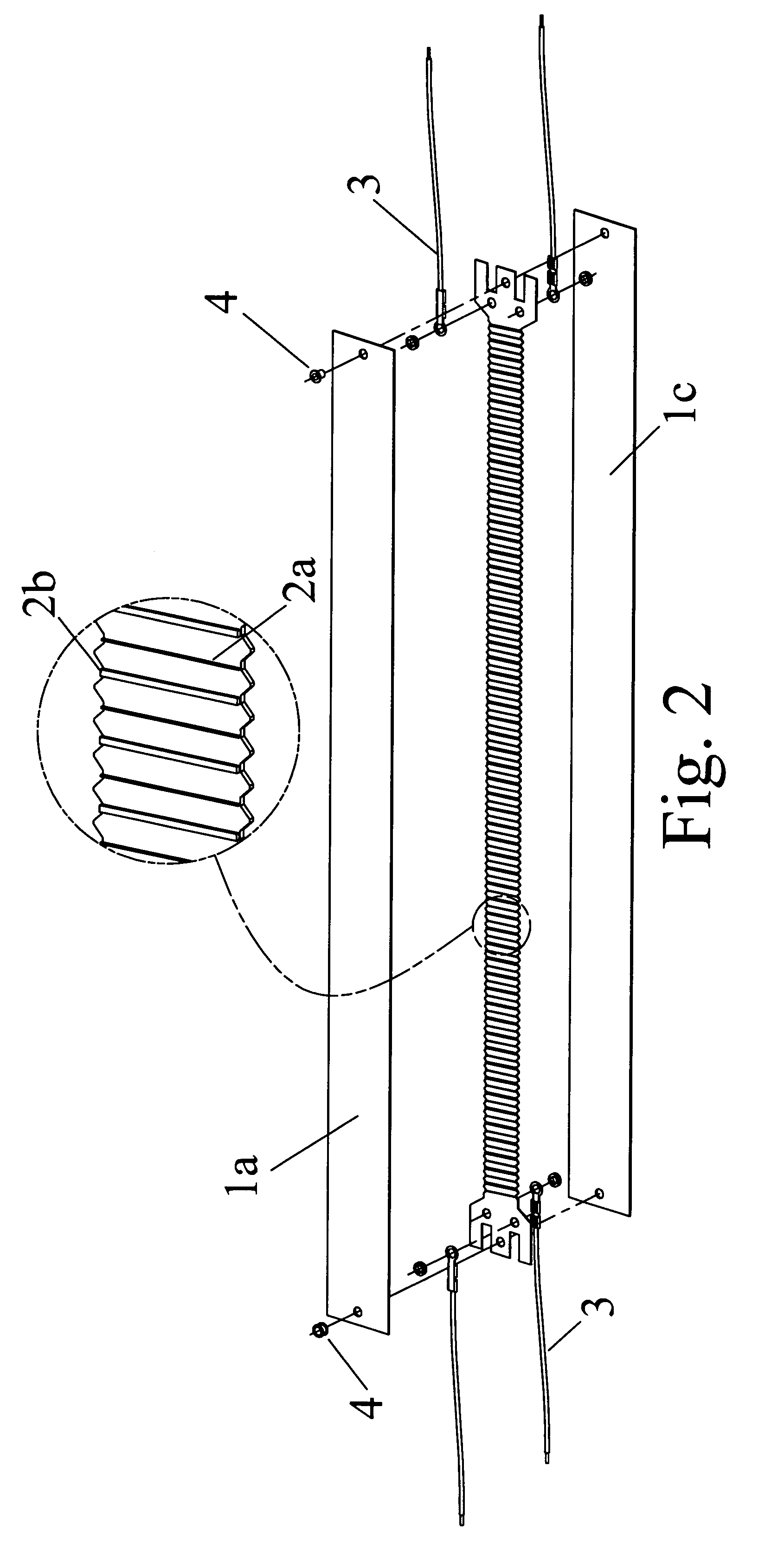
[0015]FIG. 2 is an exploded three-dimensional view of the disclosed heating element for a laminator according to the The different between the current embodiment and the previous one is that the low-power heating filaments 2a and the high-power heating filaments 2b are disposed in an alternating way and sandwiched between top and bottom insulating materials 1a, 1c, such as two mica sheets.

[0016]As shown by the locally enlarged view, the thicker high-power heating filaments 2b and the thinner low-power heating filaments 2a are disposed alternately. When the high-power heating filaments 2b are heated to a predetermined high temperature, their power is shut down. The low-power heating filaments 2a are then turned on to maintain the temperature. When the temperature is lower than a predetermined low temperature, the low-power heating filaments 2a are turned off, and the high-power heating filaments 2b are turned on to re-heat to the required working temperature. The temperature is thus...


PUM


Abstract

A heating element that can maintain a laminator at a predetermined working temperature is disclosed. A low-power heating filaments and a high-power heating filaments are sandwiched between insulators. The high-power heating filaments are shut down once it is heated to a predetermined temperature. The low-power heating filaments are then turned on to maintain a constant temperature. When the temperature drops below a predetermined temperature, the low-power heating filaments are shut down and the high-power heating filaments are turned on to heat up the laminator. The temperature is thus maintained within a predetermined range through such cycles.

Description

BACKGROUND OF THE INVENTION[0001]1. Field of Invention[0002]The invention relates to a laminator and, in particular, to a heating element that can maintain the laminator at a predetermined working temperature.[0003]2. Related Art[0004]As is well known, the laminator is used to protect important documents such as photos and identifications. The laminated product is first inserted into a film. The heating element of the laminator radiates heat to pressing rollers. The film and the laminated product are pressed by the high-temperature pressing rollers and combined together.[0005]In the above-mentioned laminating process, two problems that are complained the most by users are long pre-heating time and inhomogeneous pressing roller temperature. The inhomogeneous pressing roller temperature results in bad laminating quality. A pre-heating time longer than five minutes makes users impatient.SUMMARY OF THE INVENTION[0006]An objective of the invention is to provide a heating element that can...

Claims


Application Information

Patent Timeline
Patent Type & Authority Applications(United States)
IPC IPC(8): H05B3/10
CPCH05B3/24
Inventor WANG, T.C.
Owner MICHILIN PROSPERITY
Why Eureka
Try Eureka