
Automatic pressing mechanism for syringe needle assembly

A pressing mechanism and injector technology, applied in metal processing, metal processing equipment, manufacturing tools, etc., can solve problems such as easy to produce defective products, unable to ensure the same stroke of two cylinders, unable to perform pressing, etc.

Inactive Publication Date: 2020-03-27
利辛县众善医药科技有限公司
View PDF0 Cites 5 Cited by
  • Summary
  • Abstract
  • Description
  • Claims
  • Application Information

AI Technical Summary

Problems solved by technology

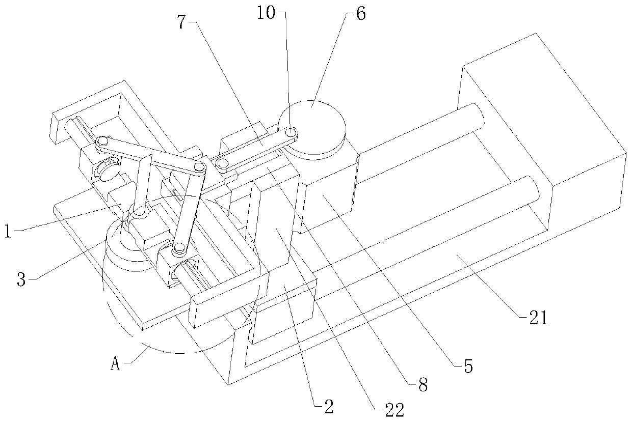
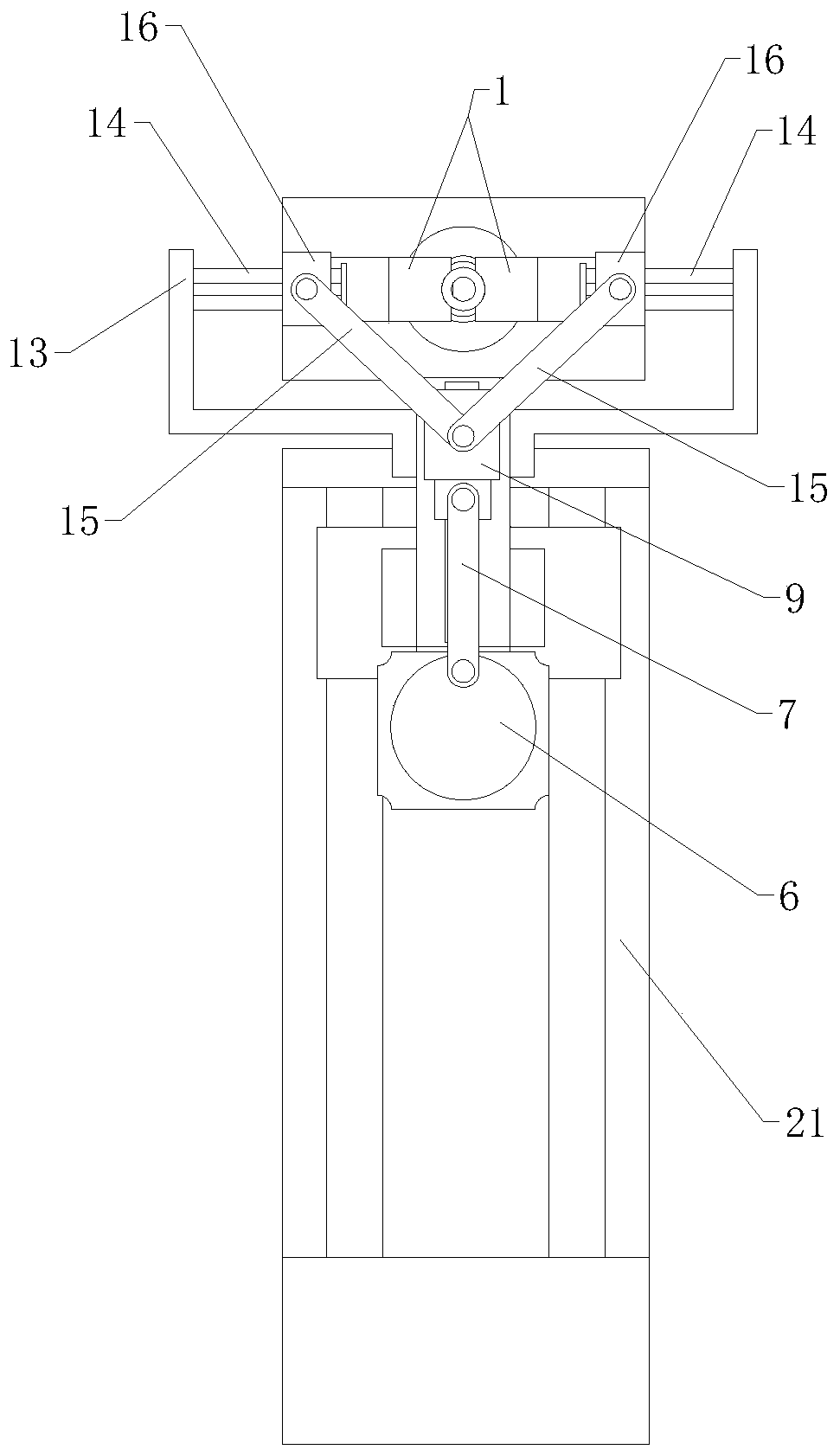
[0002] Syringes are a common medical tool. As early as the 15th century, the Italian Cattinel proposed the principle of syringes, which mainly use needles to extract or inject gas or liquid. In the production process of syringe needles, it is necessary to adjust the base of the syringe needle and The needle is assembled. During assembly, the needle needs to be inserted into the base through special conveying equipment, and then two cylinders located on both sides of the base drive the riveting blocks to press together. When the two cylinders are riveted, one cylinder is damaged. Pressing will not be possible, and the strokes of the two cylinders cannot be guaranteed to be consistent through the two cylinders, and defective products are likely to be produced during pressing. Therefore, we propose an automatic pressing mechanism for syringe needle assembly in order to solve the above problems. proposed question

Method used


Image

  • Automatic pressing mechanism for syringe needle assembly
  • Automatic pressing mechanism for syringe needle assembly
  • Automatic pressing mechanism for syringe needle assembly

Examples


Embodiment Construction

[0021] The technical solutions of the present invention will be further described below in conjunction with the accompanying drawings and through specific implementation methods.

[0022] Wherein, the accompanying drawings are only for illustrative purposes, showing only schematic diagrams, rather than physical drawings, and should not be construed as limitations on this patent; in order to better illustrate the embodiments of the present invention, some parts of the accompanying drawings will be omitted, Enlargement or reduction does not represent the size of the actual product; for those skilled in the art, it is understandable that certain known structures and their descriptions in the drawings may be omitted.

[0023] In the drawings of the embodiments of the present invention, the same or similar symbols correspond to the same or similar components; , "inner", "outer" and other indicated orientations or positional relationships are based on the orientations or positional ...


PUM


Abstract

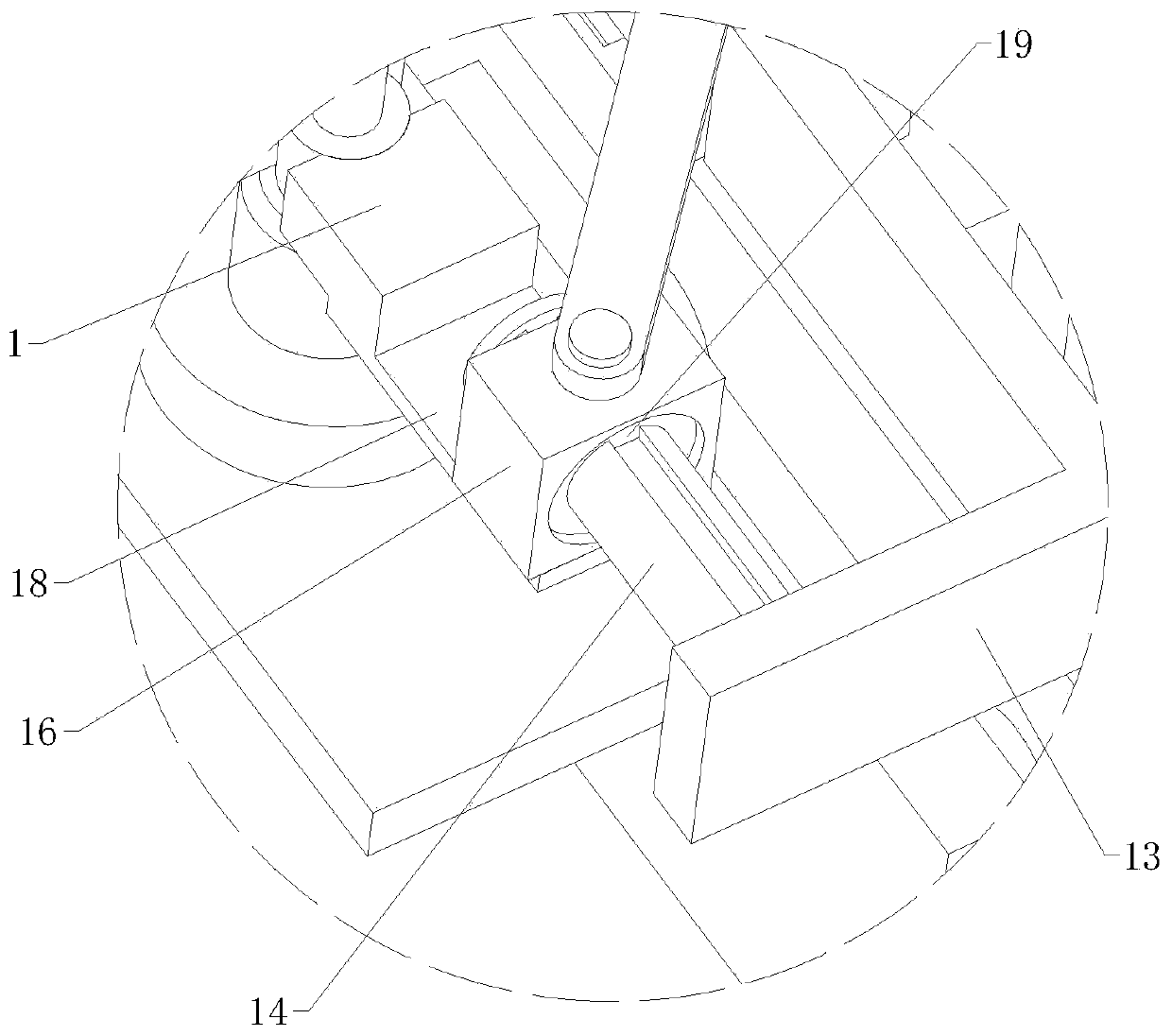
The invention relates to the technical field of syringe needle processing, in particular to an automatic pressing mechanism for syringe needle assembly. The automatic pressing mechanism comprises an accommodating jig for placing workpieces and a bidirectional pressing and riveting mechanism, the bidirectional pressing and riveting mechanism comprises a horizontal moving assembly, a rotary drivingassembly and two end pressing and riveting assemblies, the two end pressing and riveting assemblies are arranged on the two sides of the accommodating jig correspondingly, the two end pressing and riveting assemblies are symmetrically arranged, each end pressing and riveting assembly is respectively provided with a pressing and riveting block, the rotary driving assembly is located on one side between the two end pressing and riveting assemblies, the output end of the rotary driving assembly is in transmission connection with the interior of each end pressing and riveting assembly, the horizontal moving assembly is horizontal and is located below the rotary driving assembly, the horizontal moving assembly comprises a moving plate, and the interior of the rotary driving assembly is fixedlyconnected with the top of the moving plate. By means of the equipment, the two pressing and riveting blocks can be pressed at the same time in a connecting rod way, pressing quality is improved, and the cost is reduced.

Description

technical field [0001] The invention relates to the technical field of syringe needle processing, in particular to an automatic pressing mechanism for assembling syringe needles. Background technique [0002] Syringes are a common medical tool. As early as the 15th century, the Italian Cattinel proposed the principle of syringes, which mainly use needles to extract or inject gas or liquid. In the production process of syringe needles, it is necessary to adjust the base of the syringe needle and The needle is assembled. During assembly, the needle needs to be inserted into the base through special conveying equipment, and then two cylinders located on both sides of the base drive the riveting blocks to press together. When the two cylinders are riveted, one cylinder is damaged. Pressing will not be possible, and the strokes of the two cylinders cannot be guaranteed to be consistent through the two cylinders, and defective products are likely to be produced during pressing. Th...

Claims


Application Information

Patent Timeline
IPC IPC(8): B23P19/02B23P19/027
CPCB23P19/02B23P19/027
Inventor 王露露陈影
Owner 利辛县众善医药科技有限公司
Learn More